
call us
+86-18811954888
2026-09-24
You notice it before you know what it is: a matte black pole, three to five meters tall, with a slim solar panel tilted toward the sun and a small camera housing aimed down the road or across a parking lot. There is no conduit running to it, no meter box, no trench scar in the grass. It appeared in a week, and now there are six more along the same stretch of road.
Those poles are off-grid solar camera poles. Most of the ones installed in North America and Europe over the past few years are automated license plate reader stations, usually called ALPR or ANPR cameras: a camera, a cellular modem, a battery, and a solar panel packaged onto one self-powered mast. A smaller share are ordinary surveillance cameras, traffic counters, or pedestrian-counting sensors that use exactly the same power architecture. Some are not new poles at all but add-on kits clamped to utility poles or street lighting poles that already exist.
The short answer is simple. If you see a black pole with a solar panel and a camera and no visible power connection, you are looking at a self-contained, grid-independent surveillance or sensing node. The longer answer is where the engineering lives, and it is the reason some of these installations run for eight years without attention while others go dark in the first winter.
Three things decide whether any given pole performs: the power budget, the mechanical design of the pole itself, and the site conditions around it. This article walks through what the poles actually contain, why they are almost always black, how to size the solar and battery correctly, what to specify when you buy the pole, and the mistakes that cause these systems to fail in the field.
Strip away the housing and a typical solar camera pole is a stack of six functional blocks.
The first is the pole or mast: a tapered round, octagonal, or square section in hot-dip galvanized steel or aluminum extrusion, usually 3 to 6 meters tall for camera-only duty and 6 to 12 meters when the pole also carries lighting or communications equipment. Black matte powder coating is the norm.
The second is the mounting interface: a camera bracket, sometimes on a short cross arm, sometimes a vertical stem that puts the lens 300 to 900 millimeters off the pole axis. The offset matters, because the pole itself can occlude part of the field of view if the camera is mounted too close.
The third is the power source: a rigid monocrystalline panel rated somewhere between 20 W and 200 W, or a flexible panel laminated onto a curved surface when the design calls for a low-profile look. Panels are usually tilted 15 to 45 degrees and oriented toward the equator, with the tilt tuned to latitude and winter sun angles rather than to the best summer output.
The fourth is energy storage: a sealed lithium iron phosphate (LiFePO4) pack, occasionally a lead-acid or absorbed glass mat battery in older or lower-cost builds, typically 12 V or 24 V with 20 to 200 Ah of capacity. It sits in a lockable enclosure, often at the base or mid-height with a handhole for access.
The fifth is the charge controller and power conditioning: a maximum power point tracking (MPPT) controller in any serious installation, a pulse-width modulation controller in cheaper ones, plus fusing, surge protection, and a low-voltage disconnect to protect the battery from deep discharge.
The sixth is communications: a cellular modem on LTE or 5G, sometimes a small omnidirectional antenna, occasionally a Wi-Fi or LoRa radio for short-range links, and a local buffer so that data survives a network outage and uploads later.
Functionally, these poles fall into three families, and knowing which one you are looking at tells you who owns it and what it does with the data. License plate readers capture plate characters plus vehicle characteristics such as make, color, and type, along with a timestamp and a location tag, and typically upload metadata rather than continuous video. General surveillance poles stream or record video on motion triggers. Counting poles measure traffic volume, speed bins, or pedestrian flow and are common near intersections, trailheads, and campus perimeters.
One point often surprises people: many of these systems are deliberately designed not to keep video. A plate reader may store a small image of the plate and the vehicle for a defined retention window and discard everything else. The retention period is a policy decision made by the operator, not a technical limit of the pole, and it is usually the single most important thing to clarify before installation.
The color is not a style preference. Matte black solves three practical problems at once.
First, glare. A glossy or light-colored housing near a camera lens can bounce stray light into the optics, especially at sunrise, sunset, and under headlights. Cameras that must read a plate at night depend on contrast; a matte black surround reduces internal reflections and keeps the lens hood working as intended.
Second, infrared behavior. Many of these systems use infrared illumination or infrared-sensitive sensors. Dark, matte coatings with low specular reflectance behave more predictably in the near-infrared than bright or metallic finishes, which can produce hot spots in the frame.
Third, visual integration. A black pole against tree line, asphalt, or a dark sky reads as infrastructure rather than as a bright object that draws attention. Municipalities and neighborhood associations frequently ask for black for exactly this reason, and it also hides the dirt film that builds on any horizontal surface outdoors.
The trade-off is thermal. A black surface absorbs solar radiation, and a sealed enclosure in direct summer sun can run 15 to 25 degrees Celsius above ambient. That matters for two components: the battery, which ages faster above roughly 40 degrees Celsius, and the camera electronics, which can throttle or reset when hot.
Good designs handle this in specific ways. The pole and the camera housing may be black while the battery box is a light gray or white, or is mounted in the shaded side of the pole. The camera housing often includes a separate sun shield with an air gap. The battery enclosure is vented or, better, sealed with a pressure-equalizing membrane that keeps water out while allowing thermal expansion. If you are specifying a pole, ask where the battery sits and what the expected internal temperature is at the site's design ambient, typically 40 to 45 degrees Celsius for most temperate and subtropical projects.
The coating itself is a specification, not a color chip. On steel poles the usual stack is hot-dip galvanizing to a minimum of 86 micrometers (about 3.4 mils) followed by a polyester powder coat in the 60 to 120 micrometer range, with a salt-spray rating that matches the site's corrosivity category. Coastal and industrial sites need more; inland residential sites need less. Cut edges, drilled holes, and weld zones must be re-sealed, because that is where coating systems fail first.
Every solar camera pole is a small energy-balance problem. The camera and modem consume energy continuously; the panel replenishes it for a few hours a day. If the arithmetic does not close in December, it does not matter how well it closes in June.
Start with consumption. A camera running 24 hours a day at an average of 4 to 8 watts, a cellular modem averaging 1 to 2 watts, and controller losses of a few tenths of a watt add up quickly. A typical single-camera node lands between 120 and 200 watt-hours per day. Add a second camera, a radar module, or continuous video streaming and you can double or triple that figure.
Then look at harvest. A 120 W panel in a location with 3.5 peak sun hours per day, derated to 75 percent of nameplate for temperature, wiring, controller efficiency, and dust, delivers roughly 315 watt-hours per day in a good month. The same panel in January at a northern latitude might deliver 120 to 160 watt-hours. That single ratio explains why so many undersized installations die in their first winter.
Finally, size the battery for autonomy, meaning the number of consecutive dark days the system survives. Three to five days is a common design target for critical infrastructure; two days is common for low-cost consumer-grade nodes. LiFePO4 cells tolerate deeper discharge and more cycles than lead-acid, which is why they dominate new builds, but they also cost more up front and behave poorly below freezing unless a heater or a self-heating cell is specified.
The modem is the second-largest load and the most common source of ongoing cost. A single plate-read event with a compressed image is on the order of 50 to 200 kilobytes; pure metadata events are a few kilobytes. An installation that uploads a few thousand events a month may fit inside 5 to 10 GB of data, while one that streams video or uploads full-frame images can consume 50 GB or more. Signal strength drives power consumption too: a modem fighting for a marginal connection can draw several times the average current of one with good signal, which quietly destroys the power budget.
Do a signal survey at the exact pole location before fabrication. Not at the street corner, not on the roof of the nearest building, but where the pole will stand and at the height the modem will sit. If the signal is weak at pole height, the fix is either a taller pole, a directional antenna, or a different site, and it is far cheaper to discover this before the foundation is poured.
A solar camera pole carries a panel and a camera, which means its effective projected area is much larger than the pole's own silhouette. Wind load calculations must include the panel and the camera bracket, not just the mast. In exposed locations, gust loading on a bracket-mounted panel is the load case that governs wall thickness and base plate design.
Vibration is the second mechanical risk. A camera that moves a fraction of a millimeter in the wind produces blurred plates at night, which looks like a software problem but is a mechanical one. Brackets should be stiff, fasteners should be stainless and vibration-resistant, and cable should have a service loop so it never becomes the structural element that resists motion.
Access matters for total cost of ownership. A pole with a hinged base that tilts down for service saves far more over a decade than it costs to add. If the pole does not tilt, the maintenance plan has to include a bucket truck or a ladder every time a battery, controller, or SIM card is replaced.
Four deployment types look nearly identical from the sidewalk but differ sharply in power demand and ownership. The table below gives field-typical ranges, not guarantees, since camera model, duty cycle, and latitude move these numbers considerably.
| Deployment type | Typical pole height and finish | Daily energy need | What it records | Usual owner |
|---|---|---|---|---|
| Solar license plate reader | 3 to 5 m, matte black steel or aluminum, camera on a 0.3 to 0.9 m bracket | 80 to 200 Wh | Plate characters, vehicle attributes, timestamp, location tag | Police departments, neighborhood associations, retail centers, apartment operators |
| General surveillance camera | Existing utility or lighting pole with an add-on bracket, or a new 4 to 6 m pole | 40 to 150 Wh | Motion-triggered video clips or continuous low-frame-rate video | Municipalities, campuses, construction sites, industrial yards |
| Traffic or pedestrian counter | 2.5 to 4 m slim pole, often gray or black | 5 to 40 Wh | Vehicle counts, speed bins, classification, pedestrian flow | Transportation agencies, planning departments, developers |
| Solar lighting pole with camera | 4 to 8 m integrated solar pole with lamp head and camera stem | 200 to 600 Wh | Lighting duty plus video or plate reads | Cities, industrial parks, resorts, logistics facilities |
The practical takeaway is that a pole built for a 20 Wh counter will fail immediately if a 150 Wh camera and modem are bolted to it, and a pole built for a 600 Wh lighting-and-camera node is expensive overkill for a counting sensor. Match the structure to the load before you match it to the site.
The pole is the cheapest part of the system and the cause of most long-term problems. A camera pole is not a street lighting pole with a bracket added; it has different stiffness, access, and corrosion requirements.
Steel versus aluminum is the first decision. Hot-dip galvanized steel offers the highest stiffness per dollar and is the default for poles above about 5 meters or where wind loads are significant. Aluminum is lighter, easier to ship in volume, resists corrosion well in coastal air when properly finished, and is often used for integrated solar pole designs where the pole body also carries the panel. A 6063 or 6061 aluminum extrusion in a round or polygonal profile can hide wiring in an internal channel, which is a genuine advantage on a pole that must remain visually clean.
Wall thickness on steel camera poles typically runs 3 to 6 millimeters depending on height, projected area, and design wind speed. Design wind speeds of 100 to 160 km/h are common for municipal work, and some jurisdictions require higher. The base plate is usually 12 to 20 millimeters thick with gussets, anchored to a concrete foundation with M20 to M30 anchor bolts set from a template that matches the pole's bolt circle exactly. Off-by-a-few-millimeters anchor bolt placement is one of the most common and most expensive field problems there is.
Every pole needs a handhole, typically 100 by 250 millimeters, positioned for access to the wiring chamber and fitted with a cover that does not leak. Inside, there should be a grounding lug bonded to the pole body, and a service loop of cable long enough to pull the controller out to where a technician can work on it. Grounding is not optional on a pole carrying a camera, a modem, and a solar panel: lightning-induced surges travel along the panel frame and the mast, and the discharge path has to be designed rather than improvised.
For installations where maintenance access is difficult, a hinged or tilt-down pole is worth the extra cost. The hinge is at the base, the pole tilts down with a winch or by hand after removing two bolts, and every service task becomes a ground-level job.
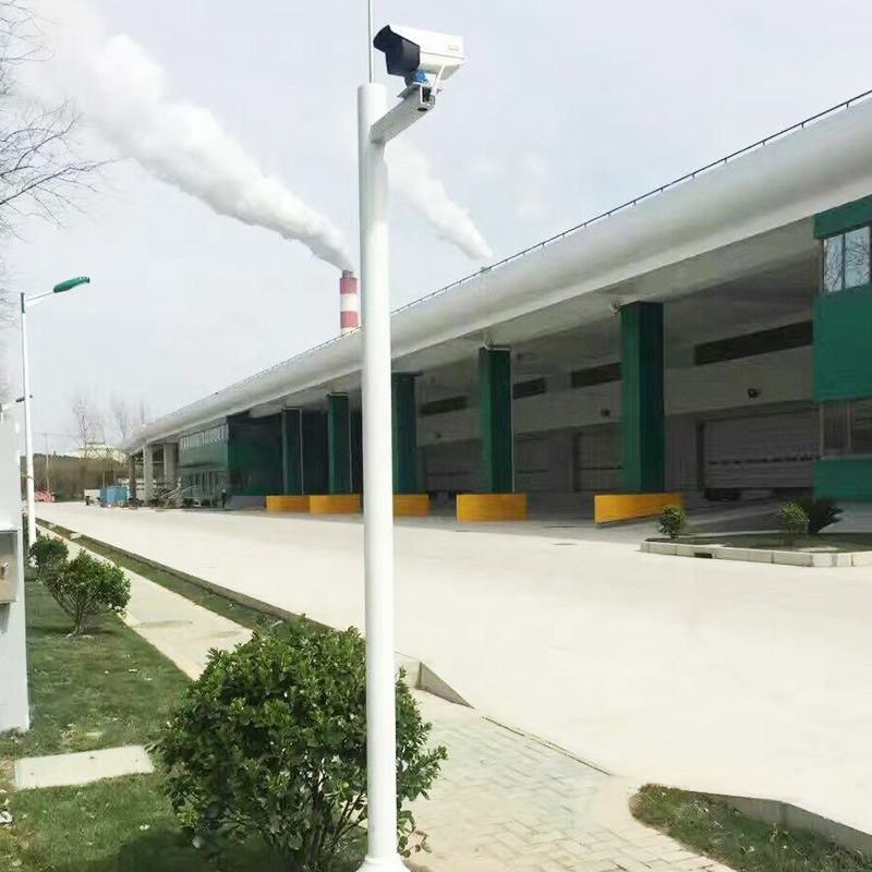 Road Safety Support Traffic Street CCTV Monitor PolesTraffic CCTV Monitor Poles – designed for surveillance and security, these poles provide a durable and stable platform for installing CCTV cameras and monitoring equip...View Product →
When the pole also carries camera brackets, cross arms, or signal equipment, the design has to be treated as a traffic and surveillance structure rather than a lighting structure. That means reviewing the mounting interface, the cable routing, the anti-theft fastener specification, and the finish system together, so the camera does not end up mounted on a mast whose coating fails at the drilled holes within three years. Manufacturers with in-house fabrication and galvanizing control, plus a documented custom fabrication process, can usually deliver that level of integration more reliably than a trading company reselling generic masts. It also pays to check whether the supplier can read a customer drawing, produce a sample, and confirm the wind load and finish spec in writing before the order is placed.
Most field failures traced back to power come from a single mistake: the system was sized for average conditions rather than for the worst month. The worked example below shows the arithmetic for a mid-latitude site with a single camera node.
| Item | Value | Notes |
|---|---|---|
| Camera average draw | 6 W | Continuous operation, night infrared duty included |
| Cellular modem average draw | 1.5 W | Periodic uploads, moderate signal strength |
| Controller and conversion losses | 0.3 W | MPPT idle consumption plus conversion loss |
| Total daily consumption | about 187 Wh | 7.8 W average multiplied by 24 hours |
| Panel nameplate | 120 W | Tilted to latitude plus 10 degrees for winter gain |
| Daily harvest in a good month | about 315 Wh | 3.5 peak sun hours, 0.75 system derate |
| Daily harvest in the worst month | 120 to 160 Wh | Short days, low sun angle, snow and dust losses |
| Battery usable capacity | about 1,024 Wh | 12.8 V, 100 Ah LiFePO4 at 80 percent depth of discharge |
| Autonomy with no sun at all | about 5.5 days | Usable capacity divided by daily consumption |
Read the table with the worst month in mind. When harvest drops to 140 Wh against a 187 Wh load, the battery covers the deficit, but only for a limited number of consecutive cloudy days. If the site has a 10-day stretch of heavy overcast in winter, the 120 W panel and 100 Ah battery are too small, and the fix is either a larger panel, a larger battery, a lower-power camera, or a reduced duty cycle for the modem.
Several smaller factors shift the numbers in practice. Panel soiling from dust, pollen, and bird droppings costs 5 to 15 percent of harvest and is worse on horizontal or shallow-tilted panels. Temperature derating costs roughly 0.35 to 0.45 percent of panel output per degree Celsius above 25 degrees, which matters most in hot, sunny locations where the panel itself gets very warm. Cable voltage drop between the panel and the controller is a real loss on long runs and argues for a higher system voltage or heavier conductors. For a broader view of how these same design rules apply across outdoor solar lighting and power systems, the principles of solar-powered street lighting systems translate directly to camera poles, since both are standalone energy systems with a load profile that never switches off entirely.
On the controller side, insist on MPPT rather than PWM wherever the panel is more than a few tens of watts. The efficiency difference between the two is often 15 to 30 percent of harvested energy, which is the difference between a system that recovers after a cloudy week and one that does not.
Site work determines performance as much as hardware does. The following items are cheap to check during planning and expensive to correct later.
A standalone camera pole is usually the first solar structure an organization buys, and almost never the last. Once a site has a validated power budget, a proven mounting height, and a working cellular link, the same design language extends to lighting, seating, charging, and signage. Combining functions on one mast or one piece of street furniture cuts civil work, foundations, permits, and maintenance visits, which are often the largest line items after the first installation.
The most common combination is camera plus lighting. A solar lighting pole with an integrated camera puts the surveillance point at the height and angle a lighting pole already occupies, and it uses the same panel and battery to serve both loads. The power budget is larger, but the incremental cost over a lighting pole alone is much smaller than the cost of two separate foundations and two separate masts.
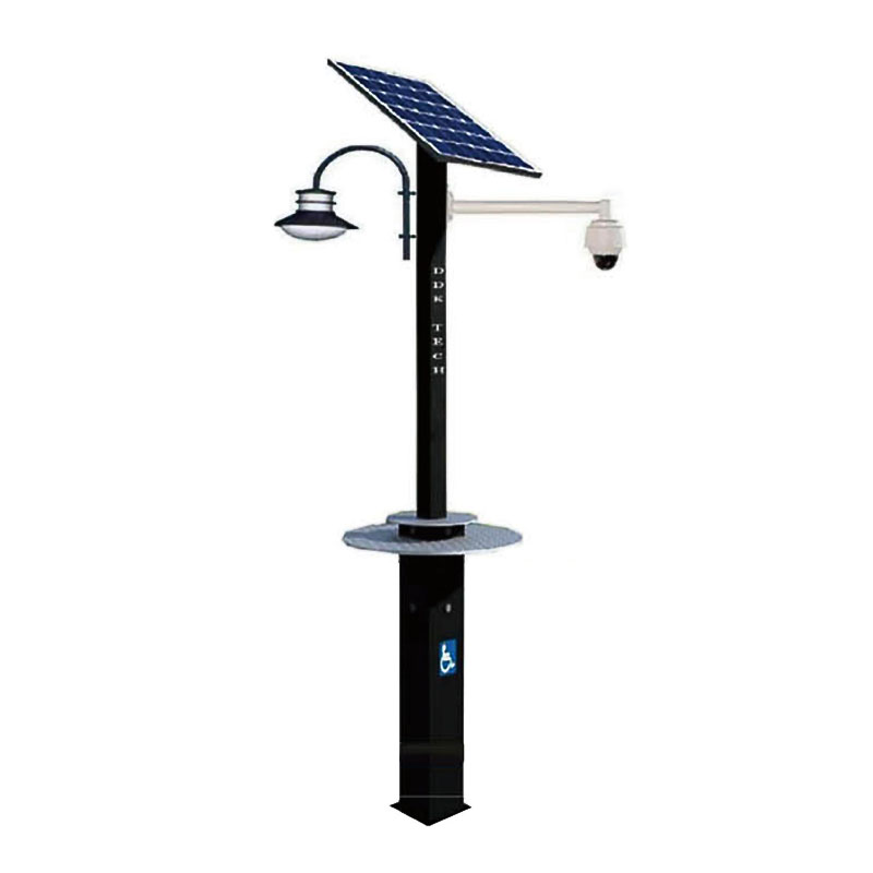 DDK-GB2000 Customized Solar Charging Station with CCTV and LampsThe DDK-GB2000 custom solar charging station integrates monocrystalline silicon solar panels to provide reliable charging for electronic devices through USB and wirele...View Product →
Public-space charging and surveillance can also share a structure. A solar charging station with integrated cameras and lamps covers several needs at once: a place to sit or plug in a device, illumination after dark, and a monitoring point for the surrounding area. These are common in parks, transit stops, plazas, and campus courtyards where running grid power to each individual fixture is impractical or prohibitively expensive.
For corridor-scale projects, integrated solar poles that carry the panel, battery, controller, and lamp head inside a single extruded aluminum body are the cleanest option visually and the easiest to standardize across a long stretch of road or a walking path. They also reduce the number of small parts that a maintenance crew has to track, which matters when a portfolio grows to dozens or hundreds of units.
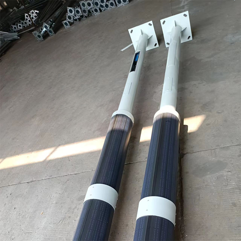 DDK-SSPL-2000 Cylinder Solar Pole Single/Double Arms And Street LED LampsDDK-SSPL-2000 solar pole is a highly customized model. The solar pole has a very large range of usage. Can be used for street lighting, CCTV monitoring, landscape ligh...View Product →
The planning lesson is to design the whole site's solar power standard at once: one system voltage, one battery chemistry, one controller family, one mounting interface, and one set of finish and fastener specifications. That consistency is what keeps a growing deployment serviceable five years later.
The following checklist is written so that it can be lifted into a request for quotation with minimal editing. Each line is something that has caused a real problem in the field when left unspecified.
Almost every failed solar camera pole fails for one of a short list of reasons, and each has a known countermeasure.
Buyers are often surprised that two poles of the same height can differ in price by a factor of two. The difference is rarely the steel alone. Pole mass, wall thickness, base plate size, and the number and complexity of brackets all scale the material and fabrication cost. Galvanizing is priced by weight and by batch size, so a one-off custom pole costs more per kilogram than a standard profile run in quantity.
Solar and storage dominate the electrical cost. Panel wattage is a relatively cheap upgrade compared with battery capacity, which is why oversizing the panel slightly is usually the better first move when the power budget is marginal. Lithium iron phosphate costs more than lead-acid up front but typically wins on total cost of ownership because it tolerates deeper discharge and more cycles, and because it reduces the number of maintenance visits over the life of the installation.
Civil work is the hidden line item. A foundation, a trench for grid power, and a permit can easily cost more than the pole itself. That is the strongest argument for off-grid solar camera poles in the first place: no trench, no service connection, no utility coordination, and a shorter installation window. Where a project is on a tight schedule, the ability to ship a factory-finished pole and set it on a prepared foundation in a single visit is worth a premium.
Lead time is driven by drawing approval, material availability, galvanizing batch schedules, powder coat color runs, and battery shipping regulations, which restrict how lithium packs travel by air and add documentation to sea freight. Non-standard pole shapes and unusual colors add time because they require dedicated tooling or a dedicated coating batch. Standardizing on a small number of pole profiles and finishes across a portfolio is the single most effective way to cut both cost and lead time.
The black poles with solar panels and cameras are a simple idea executed with a deceptively deep set of details. They are self-powered sensing nodes, usually license plate readers or surveillance cameras, mounted on a mast that provides structure, power, and communications without any connection to the grid. Their matte black finish is functional, their power budget is unforgiving, and their pole design determines whether the camera still points where it should after three winters of wind.
If you are the person who has to buy one, or fifty, the priorities are straightforward. Decide the load and the duty cycle first. Size the panel and battery against the worst month, not the average. Specify the pole's wall thickness, finish system, wind load, base plate, and access method with the same rigor you apply to the camera. Check the signal and the shading at the exact location. Then write down who owns the SIM card, the retention policy, and the warranty terms, because those three items outlive everyone who was in the room when the project was approved.
Get those decisions right and the pole becomes what it was supposed to be: quiet, self-sufficient infrastructure that runs for years and is only noticed when someone asks what it is.
Related Products
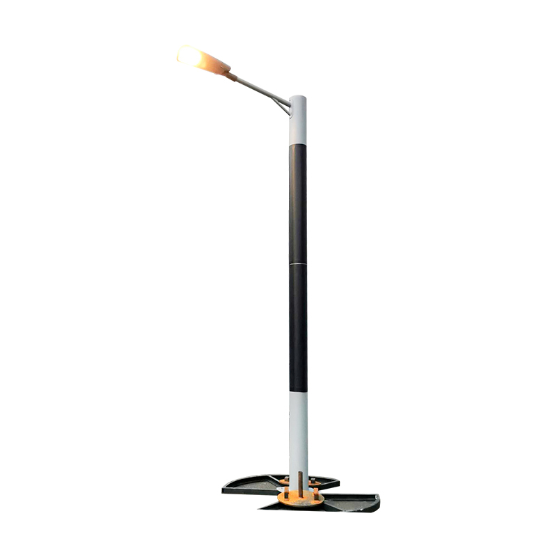 DDK-SSPL-2000 Cylinder Solar Pole Single/Double Arms And Street LED Lamps
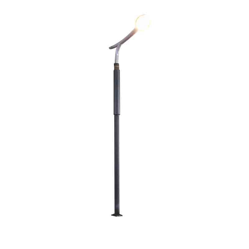 DDK-SSPL-2002 Cylinder Solar Pole With Lamp Head
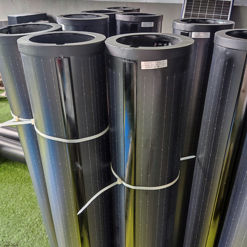 140W Flexible Solar Panel: High-Performance, Elegant and Versatile Power Solution for Lighting Poles and Park Lightings
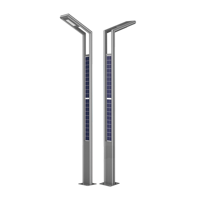 DDK-GN003 Double Sides Integrated Solar Aluminium Pole
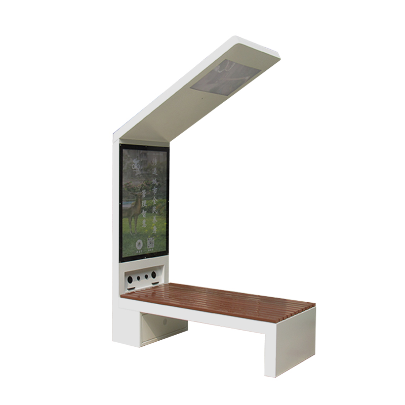 DDK-2000A Charging WIFI Solar Bench Outdoor Bench with Roof on the Top
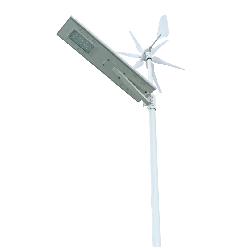 DDK G01 Solar&Wind Hybrid Integrated Optical Lens Solar All in One Light
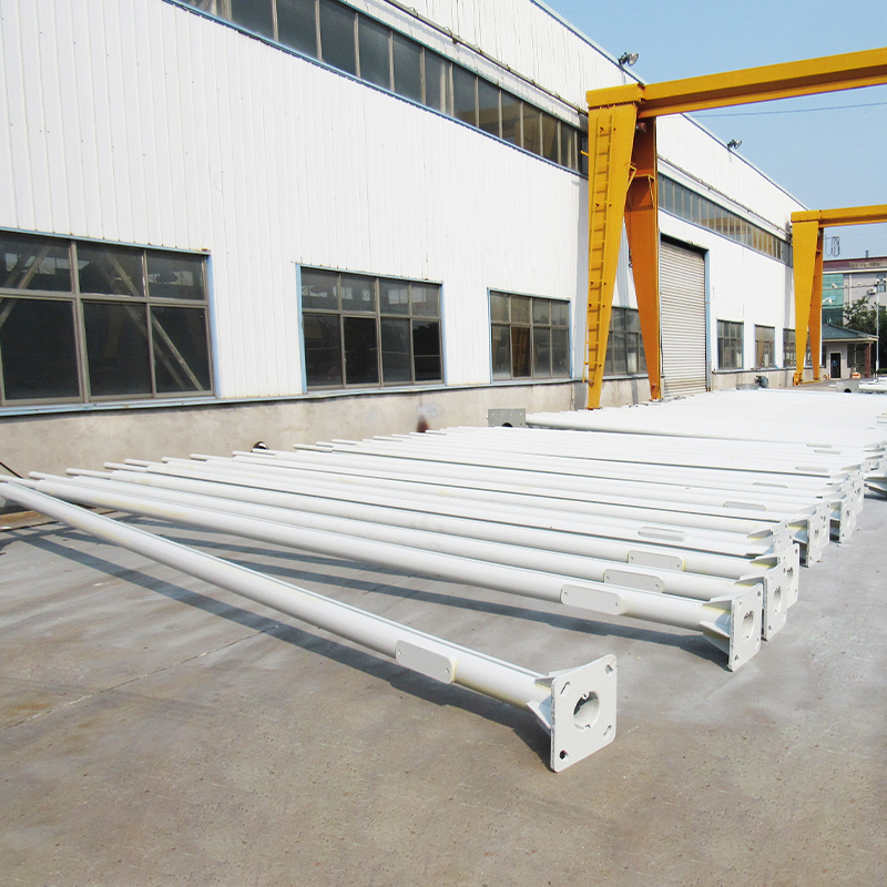 Customized Round Hexagon Octagonal Square Steel Street Light Poles for Outdoor Lightings
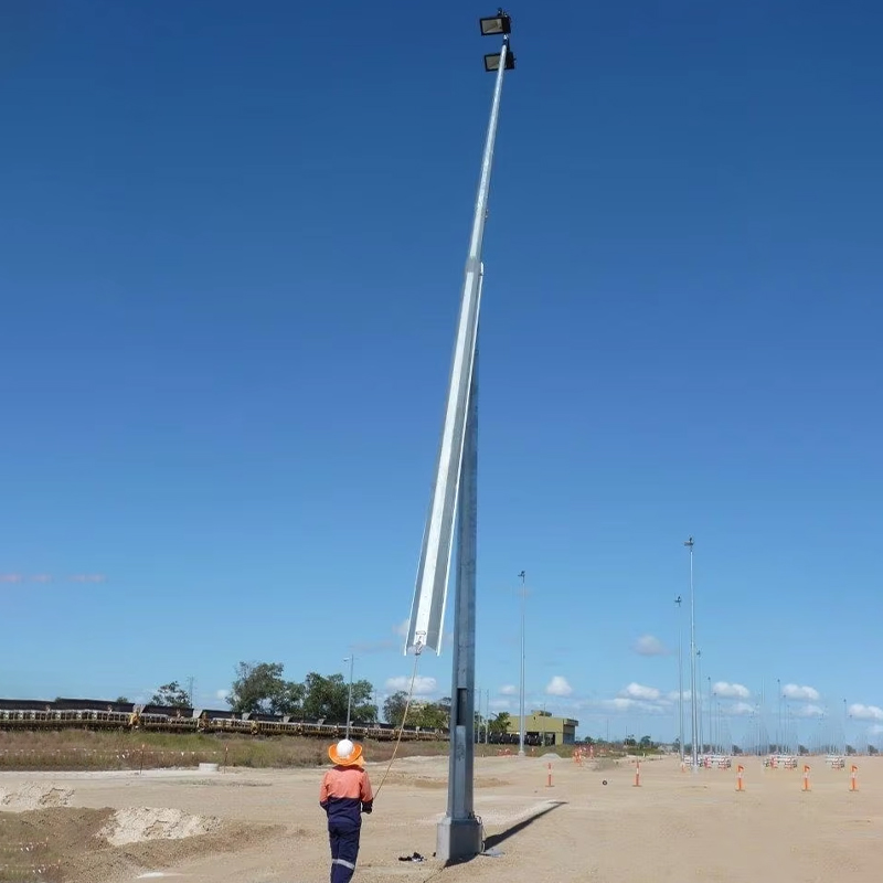 3 to 16M Galvanized Steel Hinged Poles
Contact us
180 meters south of the intersection of Nanbei Avenue and Xuba Road, Gaoyou City, Yangzhou City, Jiangsu Province, China.
+86-18811954888
ddk@cnddk.net
 English
 русский
 Español
 عربى
عربى

