
call us
+86-18811954888
2026-10-08
A distributor in West Africa ordered 60 solar energy light poles for a 4.2 km village road. Forty-nine of them worked from day one. Eleven went dark within four hours of sunset, not because the LEDs failed, but because the panels had been sized against a July irradiance number and the batteries had been given one day of autonomy. The repair bill — new batteries, larger panels, two return trips — came to more than the original hardware cost.
That failure is predictable, and it is avoidable. A solar energy light pole is a small off-grid power plant with a structural frame, and the two halves have to be designed against each other. If you buy the pole from one supplier, the panel from a second, the battery from a third, and the controller from whichever warehouse had stock, you will get a system that satisfies one requirement and quietly fails another.
The short version of what follows: size the energy budget first, size the structure second, and only then choose the configuration. Everything else — pole height, finish, panel type, battery chemistry, controller class, foundation dimensions — falls out of those two calculations. The rest of this article walks through those calculations with real numbers, tolerance ranges, wind figures, and procurement language you can paste into a request for quotation.
Strip away the marketing language and a solar energy light pole is a set of eight subsystems that must work as one:
"Complete" therefore means more than "all parts included in the carton." It means the parts have been matched: the panel has enough wattage for the worst month at the site, the battery has enough usable kilowatt-hours for the autonomy you promised the client, the pole has enough structural capacity for the extra projected area of the panel in a 40 m/s gust, and the controller has the settings to run that specific battery chemistry without cooking it in summer or refusing to charge it in winter.
The most common gap we see in incoming specifications is the last one. Buyers spend hours on lumens and colour temperature, then approve a controller whose default charge profile is set for lead-acid, on a LiFePO4 pack. The system works for a season and then loses capacity because the cell voltages never reached a proper absorption stage.
Configuration is a maintenance and risk decision far more than an aesthetic one. There are three families in practical use today.
Panel, battery, controller, and luminaire sit in a single housing at the top of the pole. Installation is fast, wiring is minimal, and the whole unit can be removed with two bolts. The trade-offs: battery capacity is limited by the housing volume, heat builds up under the panel in hot climates, and theft of the entire head is a real risk in some regions. Typical range: 20 W to 100 W luminaires with 12.8 V or 25.6 V packs up to roughly 60 Ah.
The PV material wraps around the pole shaft itself, usually across 270 to 360 degrees. Because there is no flat panel facing the sky, wind sail area drops sharply, orientation becomes almost irrelevant, and rain keeps the surface cleaner than a horizontal glass panel. Output per square metre of surface is lower than a flat rigid module, so cylinder systems suit moderate loads — path lighting, low-traffic roads, courtyards, boundary lighting — rather than 100 W highway luminaires.
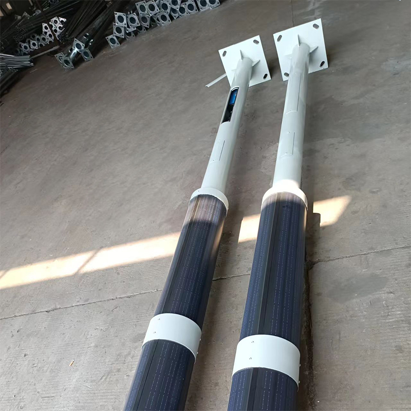 DDK-SSPL-2000 Cylinder Solar Pole with Single or Double ArmsCustomisable cylinder solar pole for street LED lamps, CCTV, landscape, garden and park lighting; integrated panel and single or double arms suit outdoor use.View Product →
The panel is mounted above the luminaire, the battery sits in a base compartment or underground vault, and the controller lives with the battery. This is the most flexible arrangement: you can oversize the battery freely, replace cells without touching the lighting head, and use standard 12 V, 24 V, or 48 V components. It also costs more in installation time and needs a tamper-resistant battery compartment.
| Configuration | Luminaire range | Battery placement | Best suited to | Main risk |
|---|---|---|---|---|
| All-in-one | 20–100 W | Inside head housing | Fast rollout, low theft areas, retrofits onto existing poles | Heat, limited autonomy, whole-head theft |
| Cylinder-integrated | 15–60 W | Base or mid-pole box | Parks, campuses, coastal and windy sites, architectural schemes | Lower harvest per footprint, harder to clean cells |
| Split | 30–200 W | Base compartment or buried vault | Roads, security lighting, high-autonomy sites, cold climates | Installation labour, cabinet theft, cable discipline |
A practical rule from project experience: if the required daily energy exceeds about 800 Wh, or the site needs more than two days of autonomy, go split. Housing the electronics separately gives you room for cells and lets you use a 25.6 V or 51.2 V pack, which halves the current for the same power and reduces resistive losses in the harness.
Everything downstream depends on one number: watt-hours per day at the load. Get this wrong and no amount of good steel or expensive batteries will save the project.
Take the luminaire power and multiply it by the hours it actually runs at full output. Modern controllers run dimming profiles, so build the profile into the arithmetic rather than assuming a flat draw.
Example: an 80 W LED on a rural road. Profile: 100 percent for 5 hours, then 40 percent for 6 hours.
Peak sun hours (PSH) are the equivalent number of hours at 1000 W/m² irradiance. Annual averages are dangerously misleading for an off-grid system. A site with a 4.9 PSH annual average may see 2.6 PSH in December, and December is when the batteries are coldest and least efficient. Design against the worst month, or accept that you must add autonomy days to cover it.
Rough reference values for a south-facing, correctly tilted array:
Divide daily load by (PSH × system derating factor). A realistic combined derating for a well-built outdoor system is 0.65 to 0.78, covering panel temperature loss, soiling, wiring, controller conversion, and battery round-trip efficiency.
Using 2.8 PSH winter and a 0.72 factor: 600 ÷ (2.8 × 0.72) = 600 ÷ 2.016 ≈ 298 W. That suggests 2 × 160 W or 1 × 320 W of panel, not the 200 W a summer-only calculation would have produced.
Battery sizing needs three inputs: daily load, autonomy days, and usable depth of discharge.
Example: 600 Wh per day, 3 days of autonomy, LiFePO4 at 85 percent usable depth of discharge.
With gel or AGM, the same site needs roughly double the nominal capacity because usable depth of discharge is closer to 50 percent and cycle life collapses past that point. That is why two systems with identical LED wattage can differ by 40 percent in cost and one of them still fails in year four.
Two corrections are routinely skipped. First, PV panels lose output as cell temperature rises: a typical monocrystalline module drops about 0.35 percent per degree Celsius above 25 °C, so a panel at 60 °C delivers roughly 12 percent less than its nameplate. Second, LiFePO4 cells should not be charged below 0 °C; in cold climates the battery needs a low-temperature cutoff or a self-heating pack, and the extra energy for heating must appear in the budget.
Adding a solar panel changes the structural problem completely. A 1.0 m² panel tilted at 30 degrees behaves like a small sail, and on a 9 m pole that sail sits at the worst possible lever arm. Structural design must treat the panel as part of the effective projected area (EPA), not as an accessory.
Basic wind pressure follows 0.613 × V², where V is wind speed in m/s and the result is in pascals. At 33 m/s (about 120 km/h) the pressure is roughly 667 Pa; at 45 m/s (about 162 km/h) it is roughly 1241 Pa. Multiply by the projected area and a shape factor — 1.2 to 1.5 for a tilted flat panel, depending on tilt and edge effects — and you get the force the pole must resist.
Example: a 1.0 m² panel at 1.3 shape factor in 40 m/s wind gives about 1275 N, or roughly 130 kg of lateral force, applied at 8 m above the foundation. That is a bending moment of about 10 kN·m before you add the luminaire and the pole itself. A 6 m decorative pole with 2.5 mm wall thickness is not the same product as a 9 m road pole with 4 mm wall thickness, and no amount of paint changes that.
Steel dominates for road and area lighting: Q235B for standard poles, Q355B where higher yield strength is needed at greater heights or in high-wind zones. Typical wall thicknesses in proven designs: 3.0 mm for 6 m poles, 3.5–4.0 mm for 8–9 m, 4.0–5.0 mm for 10–12 m. Aluminium has a place in garden and decorative ranges because it resists corrosion without coating and can be extruded into shapes that carry wiring internally — good for integrated solar designs where the panel wraps the shaft.
For steel poles, hot-dip galvanizing to ISO 1461 with a 70 µm minimum average coating on steel 3 mm and thicker is the baseline for outdoor service. In coastal or industrial atmospheres classified C4 or C5-M under ISO 9223, add a powder coating of 60–80 µm over the zinc, and specify that cut edges, weld seams, and drainage holes are properly treated. A pole that rusts at the base plate weld in year three is almost always a preparation failure, not a coating thickness failure.
Panel selection is a compromise between harvest per square metre, wind behaviour, aesthetics, and cleaning.
Still the reference for output: 20–23 percent module efficiency, 25-year performance warranties common, and predictable temperature behaviour. On a pole, the module is usually mounted on a top bracket or a side bracket at 10–30 degrees of tilt. It needs to face the equator, which means the pole orientation matters at installation, and it collects dust, leaves, and bird droppings on the upper surface.
Flexible modules use the same monocrystalline cells laminated onto a thin polymer substrate with an ETFE or similar front sheet. A 120–140 W unit typically covers 1.1–1.4 m² and bends to a radius that allows it to be fixed onto a curved surface or a cylinder. They weigh far less than glass modules, which reduces the moment at the top of the pole, and they can be bonded to the shaft where a rigid frame would be impossible. The trade-offs are higher cost per watt, a shorter realistic service life in harsh UV environments, and greater sensitivity to handling damage during installation.
Flexible panels are where integrated solar pole design becomes interesting: a curved or wrapped surface removes the orientation problem, reduces wind sail, and lets a designer put generation capacity where a flat module would look wrong. For a closer look at where that approach pays off, our team has written about the advantages of flexible solar pole lights in real installations.
Wrapping cells around the shaft gives partial generation from almost every direction, which is useful for poles that cannot be rotated — for example, replacements on an existing foundation. The penalty is real: a curved surface receives less direct irradiance per unit area than a well-tilted flat module, and the effective area is limited by the pole circumference. A 140 mm diameter cylinder presents roughly 0.44 m² per metre of height at full wrap, so a 3 m wrapped section gives about 1.3 m² of surface — not all of it productive at a given sun angle.
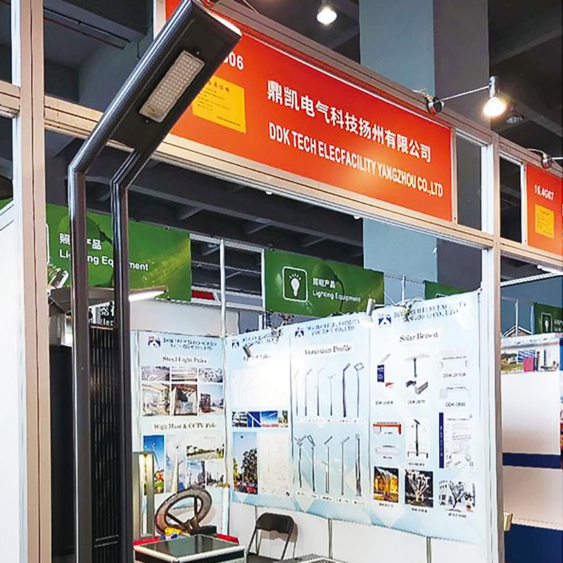 DDK-GN003 Double-Sided Integrated Solar Aluminium Pole LightDouble-sided integrated aluminium pole light with 20W/30W lamp options, 80W solar panel, 40Ah battery and IP65 rating for outdoor pole lighting.View Product →
Fixed tilt should be roughly the site latitude for year-round performance, or latitude minus 10 degrees where winter harvest matters most. Shading is the silent killer: a single cable or branch covering one cell string can cut a module's output by 40 percent or more, and on a pole the shading source is often the luminaire arm itself. Check the sun path against the arm, the pole, and any adjacent trees before approving the layout.
Batteries and controllers cause the majority of field failures in solar lighting, and they are also the parts most often reduced to hit a price target.
MPPT controllers extract 10–30 percent more energy than PWM in cold weather and low-irradiance conditions, because they decouple panel voltage from battery voltage. On a system with a 320 W array, that difference is often the entire winter margin. PWM is acceptable on small garden and path systems where the panel is already generously oversized.
Beyond the class, look for three features: a programmable charge profile that matches the exact cell specification, a load output with programmable dimming and low-voltage disconnect, and temperature compensation or a remote temperature sensor. Controllers that ship with a fixed lead-acid profile and no user-accessible settings will shorten cell life in ways the installer never sees.
The battery box is a thermal decision as much as a mechanical one. A sealed steel box in direct sun in a hot climate can push cell temperature 15–20 °C above ambient, and every 10 °C of sustained elevated temperature roughly halves calendar life. Shade the box, ventilate it, or bury the battery in a vault with a drainage sump — but decide this before the foundation is poured, not after.
Foundation work is where projects lose schedule, and it is also where structural assumptions are either validated or quietly violated.
For a 6 m solar pole, a foundation 1.2–1.5 m deep with a 500 × 500 mm cross-section in firm soil is a typical starting point; larger panels, taller poles, sandy soils, or higher wind zones push these numbers up. A widely used planning rule is depth equal to about 10 percent of pole height plus 0.6 m, then verified against soil bearing capacity and the actual overturning moment. In soft or expansive clay, the answer is usually a wider base rather than a deeper one.
Specify C25/30 or better, place the anchor cage with a template, and check bolt projection before the concrete sets. Curing is not optional: concrete reaches most of its design strength within 7 days and essentially full strength at 28 days. Setting poles and tensioning panels on day two is one of the most common causes of base-plate movement and eventual weld cracking. If the schedule is tight, use a high-early-strength mix and verify it, or plan the pole erection as a separate visit.
Poles are tall, exposed, and connected to electronics. In high-kerbaunic-activity regions, add a DC surge protection device on the panel side and a proper earth connection to the pole and the foundation rebar. A single induced surge costs a controller; a direct strike costs the whole head, and no warranty covers lightning.
Once the energy budget is secure, the lighting design decides whether the installation is accepted by the client and the community.
Modern LED luminaires in outdoor fixtures deliver 130–160 lm/W at the system level, so a 60 W luminaire should produce roughly 8,000–9,500 lumens. Treat anything below 120 lm/W as a sign of older chips or an undersized heat sink. Because solar systems are power-limited, poor efficacy directly converts into a larger panel and battery, which is the most expensive way to compensate for a cheap luminaire.
Type II and Type III distributions cover most road and path applications. The controlling metric is uniformity: average-to-minimum illuminance ratio of 3:1 or better on the carriageway, with pole spacing generally 3 to 4 times the mounting height for road lighting and closer for pedestrian areas. A bright hotspot under the pole and a dark patch halfway to the next pole fails the specification even if average lux meets the target.
3000 K is the common choice for residential roads; 4000 K suits main roads and commercial areas. Above 5000 K, discomfort glare increases without useful visual benefit for drivers. Shielded optics or flat-glass luminaires reduce upward light, which matters in jurisdictions with dark-sky requirements and also keeps the panel cleaner if it sits below the luminaire.
Specify IP65 or IP66 for the luminaire, IP67 for the battery enclosure in exposed positions, and IK08 or IK09 where vandalism or vegetation clearance equipment is a factor. Certification references worth asking for: IEC 60598 for luminaires, IEC 61215 and IEC 61730 for PV modules, IEC 62619 for lithium cells, and UN 38.3 test summaries for transport.
The same keyword covers a garden bollard and a 12 m highway mast, and the specification language should not be identical for both. The table below sets out starting points based on typical projects; each row still needs its own energy budget.
| Application | Mounting height | Luminaire | Panel / battery direction |
|---|---|---|---|
| Village or rural access road | 5–7 m | 30–60 W, 4000 K | Split system, 150–250 W panel, 100 Ah at 25.6 V, 3 days autonomy |
| Urban residential street | 6–8 m | 60–80 W, 3000–4000 K | Split or all-in-one, 250–350 W panel, 2 days autonomy |
| Park and garden path | 3–4.5 m | 15–30 W, 3000 K | Cylinder-integrated or decorative split, 60–120 W panel |
| Campus, plaza, promenade | 4–6 m | 30–60 W plus amenity loads | Split with base cabinet, 200–300 W panel, WiFi or CCTV loads added to budget |
| Coastal road or port area | 6–9 m | 60–100 W, IP66, C5-M finish | Cylinder or split with sealed enclosure, generous panel for salt haze losses |
| Cold climate, snow load | 6–8 m | 60–80 W | Split with heated or insulated battery vault, panel tilt 15–20 degrees steeper |
Two application notes that rarely make it into tender documents. First, amenity loads — CCTV, WiFi access points, USB charging, sensors — must be added to the daily watt-hour budget at their real duty cycle, not their nameplate power. A 10 W camera running 24 hours consumes 240 Wh per day, which is 40 percent of the lighting load in the example above. Second, in villages and border areas, the battery compartment is the theft target, not the panel. A 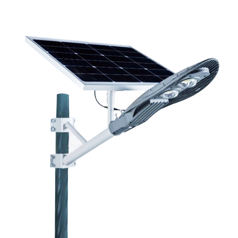 DDK-VILLAGE Solar Pole Light for Village and Wall MountingFully solar-powered outdoor light for rural streets, pathways and building exteriors, supporting pole or wall installation where grid electricity is limited.View Product → with the pack locked inside the pole base and a tamper-resistant screw set solves more problems than upgrading to a larger panel.
Solar poles are usually compared against a grid-connected alternative, and the comparison changes depending on distance to the nearest supply point.
The grid alternative has its own cost structure: trenching and reinstatement commonly run 30–80 USD per metre depending on surface, plus cable, protection devices, transformer capacity, and the recurring electricity bill. A solar energy light pole avoids all of that, which is why the break-even distance for a single pole against grid extension is often as low as 15–30 m of trenching — and much lower where the pavement cannot be cut.
Assume LiFePO4 replacement in years 8–10 under normal cycling, controller replacement in years 5–7 in humid climates, panel cleaning twice a year, and one luminaire driver replacement in year 6–8. Add those to the purchase price and compare against a grid-connected pole with a 25-year service life and a monthly energy bill. The comparison usually favours solar where trenching is involved, and usually favours grid where a supply point is within 10 m and electricity is cheap.
Asking for the energy budget sheet is the single most effective filter in a tender. Suppliers who cannot produce it are estimating, and on a 60-pole order the estimating error is larger than the price difference between two serious bidders.
Solar lighting systems do not fail suddenly. They degrade along a predictable curve, and the operator sees the symptom — shorter run time — long before the cause.
If the controller logs data — most modern MPPT units do — ask for the charge and discharge history at every service visit. A slow decline in harvest, rather than a sudden drop, points to soiling or shading. A decline in stored energy at unchanged harvest points to the cells. That single distinction saves a lot of unnecessary component swapping.
Most solar pole projects are not catalogue purchases. A municipality wants a specific arm curve and a colour that matches existing furniture. A distributor needs the pole height changed from 6 m to 7.5 m without losing the wind rating. An integrator wants the battery compartment moved from the head to the base and the panel size increased by two modules.
That kind of work is a manufacturing problem before it is a lighting problem. It requires the ability to read a customer drawing, check it against structural reality, produce a sample, and then hold the geometry across a production batch of hundreds of poles. Our own background at DDK Tech Elefacility Yangzhou Co., Ltd. sits exactly there: steel pole fabrication, aluminium profile lighting, solar pole integration, and flexible solar products, produced either from customer drawings or developed from a specification, with sampling and engineering feedback along the way. More detail on our manufacturing and customization capabilities is available if you are evaluating a build-to-print supplier.
Three practical notes for anyone commissioning a custom solar pole:
The eleven dark poles in that West African village road were not a solar problem. They were a specification problem: a summer irradiance figure used for a year-round design, and one day of autonomy sold as three. Every technical decision that follows — how thick the pole wall is, whether the panel is rigid or wrapped, whether the battery sits in the head or in the base — should trace back to two documents: an energy budget for the worst month and a wind load calculation for the complete assembly.
Get those two right and the rest of the project becomes ordinary procurement: compare coatings, compare certifications, compare warranty terms, and ask for the test reports. Get them wrong and no upgrade in steel grade or battery brand will keep the lights on past year five. If you are specifying a solar energy light pole for a project, start with the load profile, the site's winter sun, and the autonomy the client actually needs — then let the hardware follow the arithmetic.
Related Products
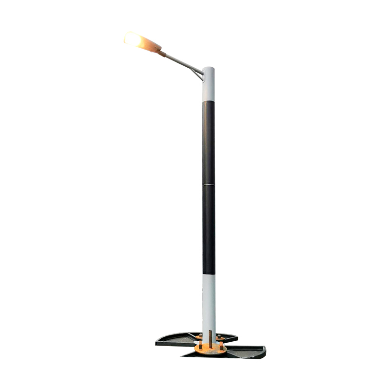 DDK-SSPL-2000 Cylinder Solar Pole Single/Double Arms And Street LED Lamps
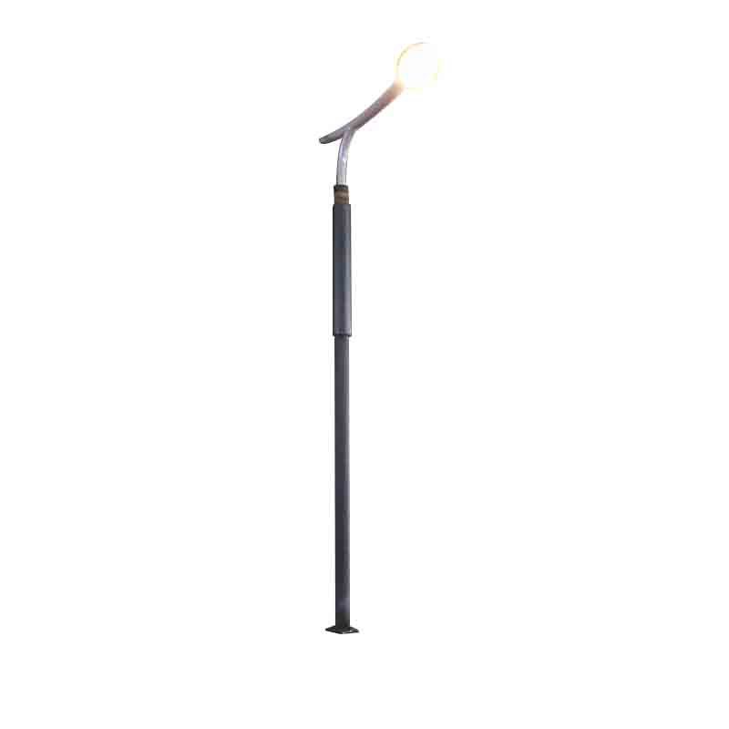 DDK-SSPL-2002 Cylinder Solar Pole With Lamp Head
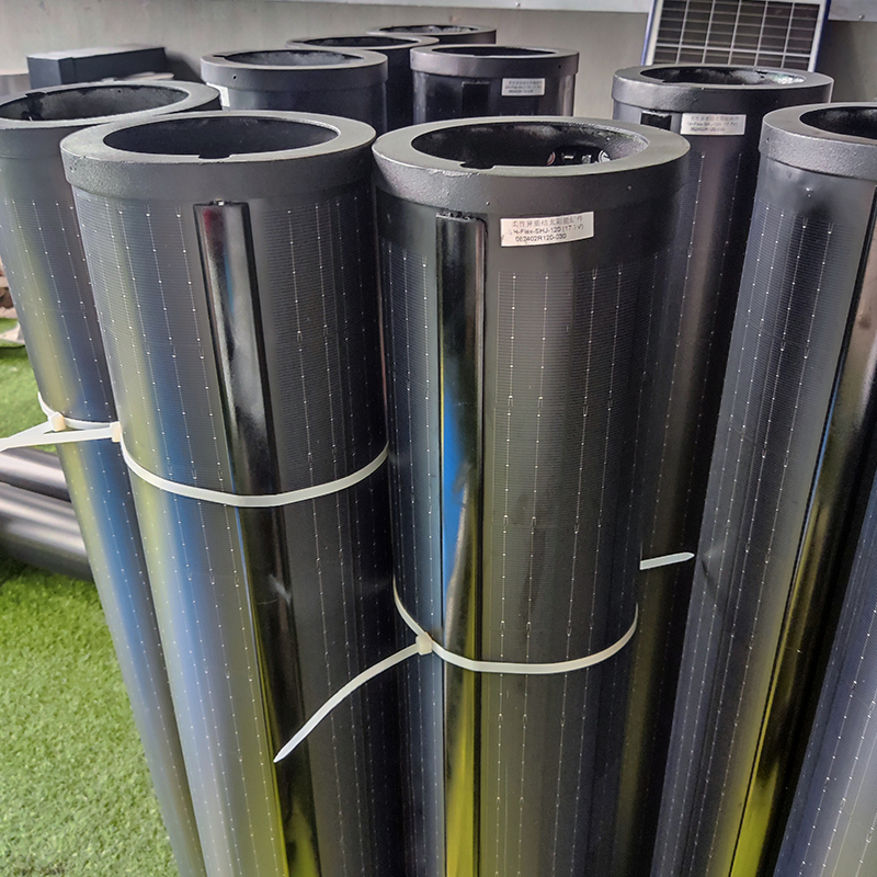 140W Flexible Solar Panel: High-Performance, Elegant and Versatile Power Solution for Lighting Poles and Park Lightings
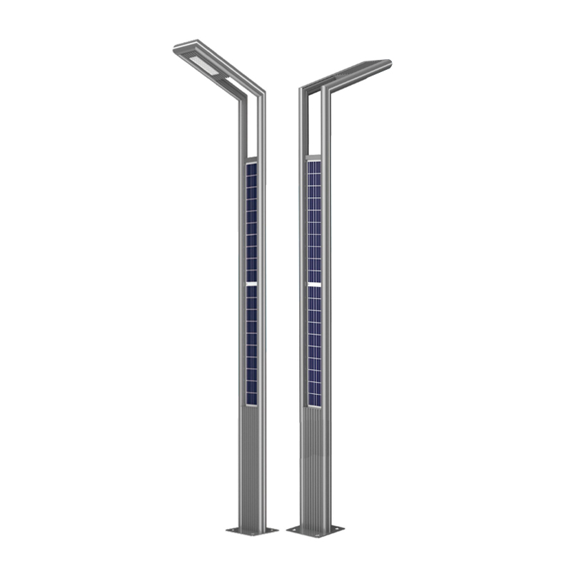 DDK-GN003 Double Sides Integrated Solar Aluminium Pole
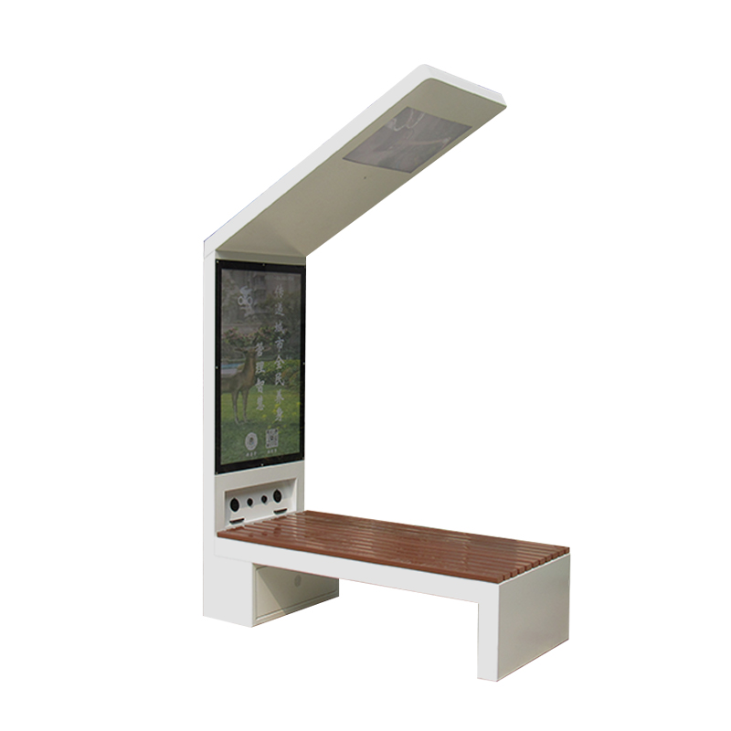 DDK-2000A Charging WIFI Solar Bench Outdoor Bench with Roof on the Top
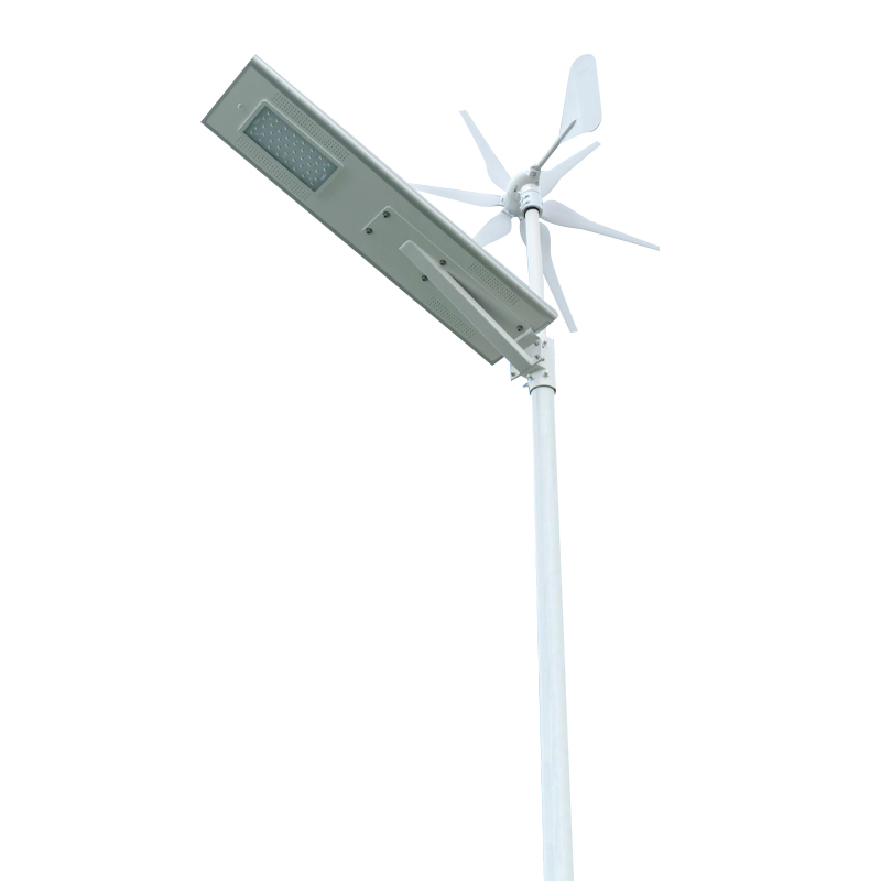 DDK G01 Solar&Wind Hybrid Integrated Optical Lens Solar All in One Light
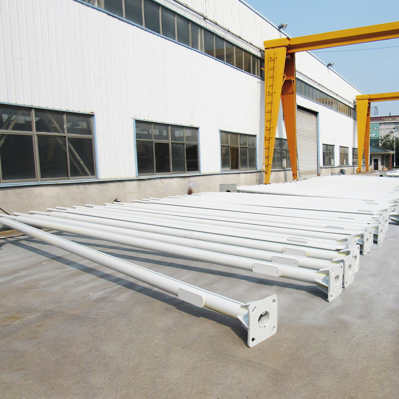 Customized Round Hexagon Octagonal Square Steel Street Light Poles for Outdoor Lightings
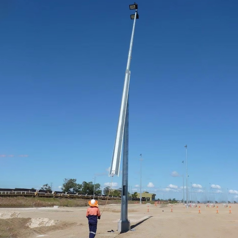 3 to 16M Galvanized Steel Hinged Poles
Contact us
180 meters south of the intersection of Nanbei Avenue and Xuba Road, Gaoyou City, Yangzhou City, Jiangsu Province, China.
+86-18811954888
ddk@cnddk.net
 English
 русский
 Español
 عربى
عربى

