
call us
+86-18811954888
2026-10-15
A project engineer sends out a request for quotation covering 30 "decorative light posts, 4 m tall" for a pedestrian promenade and 12 "street light poles, 9 m" for the connector road beside it. The quotations come back split into two packages with different base plates, different anchor bolt circles, and a note asking whether the 4 m units are meant to be direct-buried or bolted down. Nobody specified it, because everyone on the project assumed the words "post" and "pole" already carried that information.
They do not. In most lighting standards and most fabrication shops, the difference between a light pole and a light post is not a dictionary definition. It is a bundle of design assumptions: how tall the support is, how much wind load it must resist, how it is fixed to the ground, how the cable reaches the luminaire, and who signs off on it before the circuit is energised.
The short answer, before the detail: a light pole is a structural support built for roadway-scale loads, generally 6 m and up, usually hot-dip galvanised steel, and almost always anchor-bolted to a designed concrete foundation. A light post is a shorter, lighter, pedestrian-scale support, generally 1 to 5 m, often aluminium or cast metal, and frequently direct-buried or mounted on a small prefabricated base. Everything else in this article is about where that line actually sits, why it moves with wind speed and luminaire size, and what it means when you are writing a purchase order.
Before the engineering, here is the summary a fabricator would give you across the counter.
None of those five points is decided by the word you write on the drawing. They are decided by the load case, the site, and the foundation detail. That is why the terminology argument usually ends the moment somebody asks for the anchor bolt circle.
Height is the easiest signal, and it is reliable roughly 80 percent of the time. Below about 5 m, almost everyone in the industry says "post" or "garden light pole." Above about 8 m, almost nobody says "post." The genuine disagreement lives in the 4 m to 6 m band, where a decorative square pillar and a small roadway pole can be the same height while being completely different structures.
| Application | Typical mounting height | Usual industry term | Typical ground connection |
|---|---|---|---|
| Garden path, lawn, flower bed | 0.6 - 1.2 m | Lawn light, bollard, post | Ground spike or direct burial |
| Decorative streetscape, courtyard, hotel forecourt | 2.5 - 4.5 m | Post | Direct burial or small cast base |
| Park walkway, plaza, campus path | 3 - 5 m | Post, sometimes pole | Direct burial or anchor bolts |
| Residential street, car park, service road | 5 - 8 m | Pole | Anchor bolts on concrete foundation |
| Arterial road, town centre, industrial access | 8 - 12 m | Pole | Anchor bolts on concrete foundation |
| Highway interchange, port, stadium | 12 - 40 m | High mast pole | Engineered foundation, often with a bolt cage |
| Solar all-in-one unit | 3 - 8 m | Pole or post, depending on panel area | Varies; the panel usually decides |
What matters more than the number is what the support is carrying. A 5 m post holding a decorative lantern with roughly 0.15 square metres of exposed area behaves nothing like a 5 m pole holding a 1.2 m outreach arm and a 120 W LED luminaire whose housing, arm, and bracket together present 0.4 square metres to the wind. Same height, roughly triple the bending moment at the base, and completely different anchor bolts.
If you only remember one technical point from this article, make it this one: the word on the drawing does not protect you, the load calculation does. A support is sized by the bending moment at its base, and that moment is the product of wind pressure, exposed area, and the height at which the load acts. Doubling exposed area roughly doubles the moment. Raising the mounting height from 4 m to 8 m roughly doubles it again. A taller, heavier, higher-drag assembly does not just need a thicker pole; it needs a different base, a different foundation, and a different installation method.
Start with EPA. Manufacturers publish it for luminaires, and it should include the luminaire body, the arm, any photometric bracket, and any signage or camera added later. Then apply the project design wind speed from the local code, together with the exposure category and gust factor that go with the site. A sheltered inner-city plaza and an exposed coastal slip road can share a wind speed number on paper and still produce very different pressures, because ground roughness and topography change the profile with height.
This is where posts often fail quietly. A decorative post rated for a 100 km/h basic wind speed with a small lantern may be perfectly adequate, but the same post fitted with an oversized LED head, a banner bracket, or a seasonal decoration suddenly carries two or three times the design moment. If the supplier's catalogue does not state an EPA limit, ask for one in writing. A post with no declared EPA limit is an unknown quantity, not a cheap solution.
For steel poles, three variables do most of the work: section shape, wall thickness, and taper. Octagonal and twelve-sided sections give more stiffness per kilogram than round tube, which is why most roadway poles are polygonal. Wall thickness for decorative posts typically runs 2.5 mm to 3.5 mm, while roadway poles commonly run 4 mm to 6 mm, with the base section the thickest part of the shaft. Taper is usually expressed as a ratio, commonly between 1:80 and 1:120, meaning the diameter shrinks by roughly 8 mm to 12 mm for every metre of height.
Steel grade is usually S235JR or S355JR under EN standards, or an equivalent structural grade such as ASTM A572. The grade matters less than the wall thickness in most decorative work, but it matters a great deal in long spans and high mast applications, where deflection and fatigue start to govern the design rather than simple bending strength. Anyone reviewing a submission should look for the calculation, not just the steel certificate. There is a useful engineering discussion of how section shape changes stiffness and load-bearing capacity in steel light poles if you want to go deeper into that trade-off.
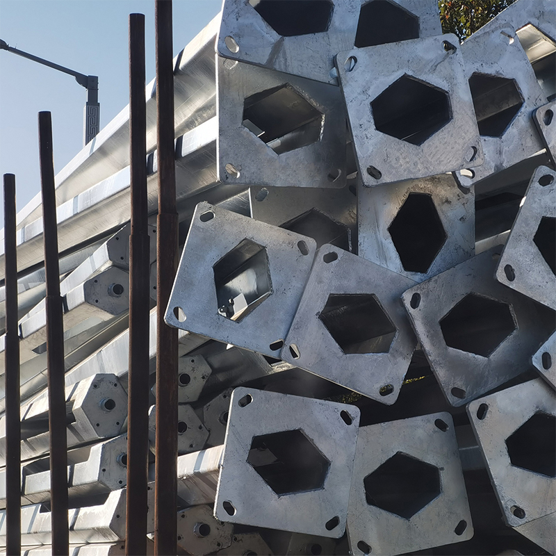 Customized Steel Street Light Poles in Round, Hexagonal, Octagonal, SquareFor street lighting projects, these steel poles offer customizable shapes, heights, and base plates; verify structural calculations and foundation design before approval.View Product →
The foundation is where the difference between a pole and a post becomes visible on site, and where most change orders are born.
A typical anchor-bolted pole uses a square or round base plate welded to the shaft, four or more anchor bolts set in a concrete foundation, and leveling nuts above and below the plate so the pole can be plumbed before grouting. Base plates on mid-height poles often run 300 mm to 500 mm square, with thickness from 12 mm to 25 mm, and anchor bolts from M16 to M30 depending on the moment. Bolt projection above the concrete is usually kept in the 60 mm to 100 mm range so there is room for leveling nuts, the plate, a washer, and a nut.
Directly buried posts work on a completely different principle. The shaft continues below grade, usually to a depth of about one third of the above-grade height, with a practical minimum around 600 mm, and is set in concrete or compacted backfill depending on soil. This is cost-effective and fast, and it is also irreversible: once the post is in the ground, changing the height means excavation.
One more detail that is easy to overlook: base covers. A decorative base cover hides the plate, bolts, and grout, and it needs to fit over the anchor bolt heads without stressing the casting. If the base cover is bought separately from the pole, check that both come from the same drawing revision.
Access is the second big functional divide, and it shows up years after handover. A pole with a handhole or access door lets an electrician open a cover roughly 450 mm to 600 mm above grade, reach a terminal block, test the circuit, replace a fuse, or disconnect a faulty driver without touching the ground. The handhole also gives the cable a defined entry point, usually through a slot in the base plate or a grommet in the shaft wall.
A typical decorative post has no handhole at all. The cable runs up the inside of the shaft from a junction box below grade or behind a paving stone, which is clean and visually discreet, but it means any fault in the connection requires excavation or pulling the head off the top. On a promenade with a hundred posts in a straight line, that difference matters for the maintenance budget.
Two related specifications are worth writing down early. First, the IP rating of the terminations and any in-line connectors, especially on coastal or irrigated sites. Second, the cable entry height and the type of gland, because a handhole that lets water pool around a gland will eventually produce a nuisance trip on a residual current device, and nuisance trips are usually blamed on the luminaire rather than the pole.
The table below summarises the practical differences most procurement teams need to capture in a specification.
| Attribute | Light pole | Light post |
|---|---|---|
| Typical height | 6 - 12 m, up to 40 m for high mast | 1 - 5 m, occasionally 6 m |
| Primary material | Hot-dip galvanised structural steel, octagonal or round | Aluminium extrusion, cast aluminium, thin-wall steel |
| Design check | Wind speed, EPA, deflection, foundation design | Catalogue rating, often with a stated maximum head size |
| Ground connection | Base plate, anchor bolts, engineered concrete foundation | Direct burial, spike, screw base, or small cast base |
| Cable access | Handhole or access door with terminal block | Usually none; cable routed through shaft or below grade |
| Typical luminaire load | 60 W to 400 W, single or double arm | 10 W to 60 W, single head or decorative cluster |
| Installation method | Mobile crane or boom truck, plus concrete work | Manual or small lifting equipment, no concrete in many cases |
| Relocatable | Yes, if the foundation is reused or replaced | Poorly; buried posts are effectively permanent |
| Inspection intensity | Structural calculation, weld inspection, galvanising certificate | Visual and functional checks, occasional load rating |
| Relative unit cost | Higher material and installation cost | Lower material cost, sometimes higher long-term access cost |
This is pole territory without argument. The support must carry a large luminaire at 8 m to 12 m, resist vehicle-induced vibration, and survive being hit by a delivery van without dropping its arm onto the carriageway. Poles here are anchor-bolted, designed for the local wind map, and usually submitted with calculations. Where the streetscape calls for a signature shape rather than a plain octagon, the same structural rules still apply, which is why shaped profiles have to be engineered rather than simply drawn. Custom profiles are produced to order rather than picked from a catalogue.
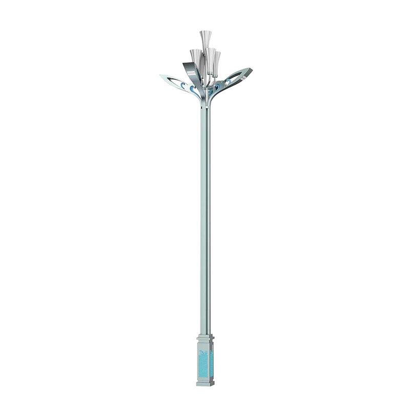 Unique Shaped Steel Light Poles for Urban and Landscape LightingWhere a streetscape requires a signature profile rather than a plain pole, these steel light poles suit urban, park, and public-space lighting.View Product →
Posts dominate here, and the design priority shifts from reach to human scale, glare control, and daytime appearance. A 3 m to 4 m retro-style post with a cast base and a lantern head is cheap to install, easy to replace head-for-head, and visually appropriate. Where designers want the lantern look at a slightly larger scale, they often move to a decorative pole of 4 m to 6 m that keeps the appearance of a post but adds an anchor-bolted base and a proper handhole. Decorative garden units in the 3 m to 6 m range sit exactly on that boundary, and the specification has to state which side of the line the project wants.
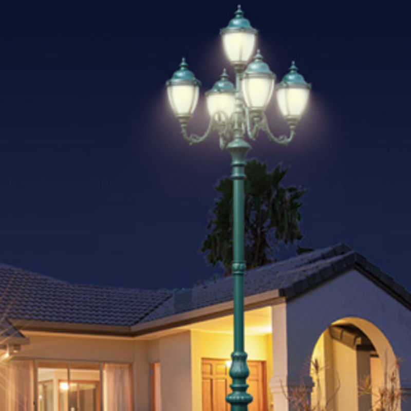 DDK-ZH-0401 Decorative Retro Garden Light Poles, 3 to 6MThese aluminum decorative poles suit parks, plazas, and residential gardens, bridging post-scale and pole-scale specifications at 3 to 6 m.View Product →
Height is chosen by coverage geometry rather than by vocabulary. A typical car park bay is illuminated from a support around 6 m to 8 m, which is pole scale for load purposes even when the drawing says "post." Where the goal is uniform illuminance across a wide apron, spacing usually pushes the designer upward in height and outward in wattage, and that combination should always trigger a load check.
Nothing here is a post. High mast poles of 15 m to 40 m use lowering rings or climbing access, engineered foundations, and often wind-induced fatigue checks that simple bending calculations do not capture. If a project uses the word "post" in a tender document for anything above 12 m, treat it as a typographical error and clarify before pricing.
Adding a photovoltaic panel changes the calculation more than adding an LED head does, because the panel is a flat plate with a large lever arm and can be rotated to face the sun. A 3 m post carrying a 1.5 square metre panel is a small sail; the same post carrying a 0.15 square metre lantern is not. This is why many solar products migrate upward into pole territory in both structure and base detail, even when they are visually the same height as a decorative post.
For off-grid installations, the sensible approach is to size the support as a pole first and check whether a post-shaped product happens to satisfy that calculation. Doing it the other way round, choosing the shape and then discovering the panel load, is how a project ends up drilling extra anchor bolts on site.
A specification does not need to be long. It needs to remove the assumptions that cause variation between suppliers. The following sequence covers the points that most often decide whether the delivered product matches the drawing.
Items one through four are what genuinely separate a light pole from a light post on a purchase order. If those four are unambiguous, the rest is administration.
Most projects do not buy a catalogue item. They buy something close to a catalogue item with a different height, a different base, a different colour, or a head that has to match a landscape architect's sketch. That is normal, and it is manageable provided the drawing you send is complete enough to price and build without interpretation.
The most useful things a buyer can send are a dimensioned elevation showing height above grade, a base detail showing the ground connection, the luminaire data, the wind and exposure requirement, and the finish colour. Everything else can be resolved by discussion. What causes trouble is a one-line enquiry that says "40 decorative posts, 4 m, grey," because every supplier will make a different reasonable assumption about wall thickness, base type, and corrosion protection, and the quotations will not be comparable.
Custom fabrication from customer drawings, including non-standard profiles, cast base covers, and matched colour finishes, is routine for an experienced outdoor lighting manufacturer, and it is worth confirming early whether a supplier can produce prototypes and one-off pieces alongside volume orders. A short note on the manufacturer's engineering and production scope is available on our manufacturing and customization capabilities page if you want to check what can and cannot be built to drawing.
So what is the difference between a light pole and a light post? In everyday speech, height. In engineering terms, load path. A pole carries a large bending moment into a designed foundation through a base plate and a set of anchor bolts, and it gives maintenance staff a handhole to work from. A post carries a small load into the ground, often through a buried shaft, and it is chosen as much for how it looks in daylight as for what it illuminates at night.
The practical rule that survives most project conditions is this: work out the bending moment at the base first, then decide what to call the product. If the calculation needs anchor bolts and a concrete foundation, you are specifying a pole, whatever the streetscape drawing says in its notes. If it does not, a post will do the job and cost less to install. Getting that order right saves a surprising amount of money, and it saves the argument at the site gate when the truck arrives.
Related Products
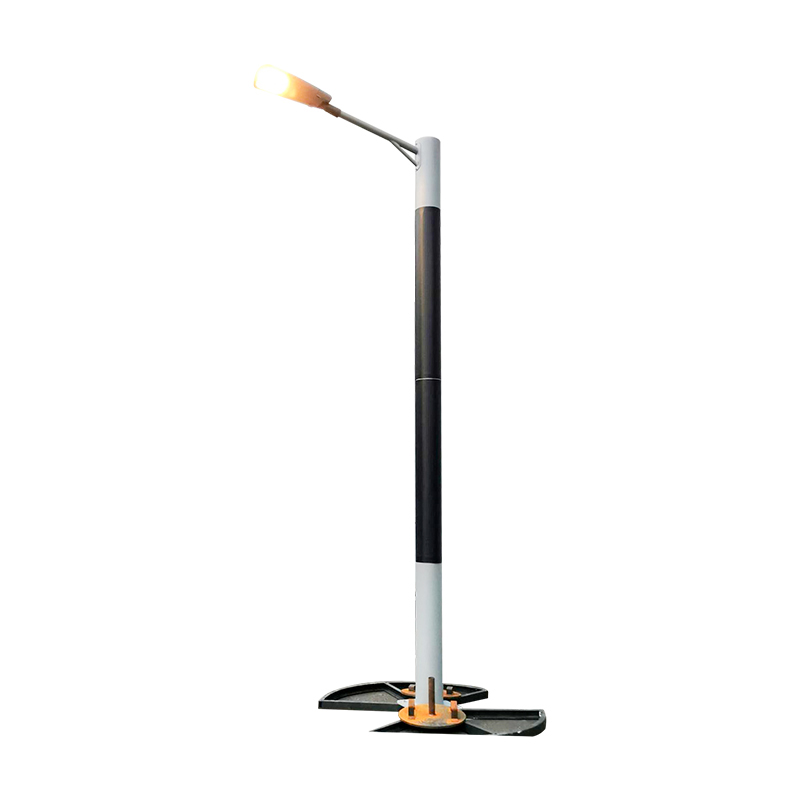 DDK-SSPL-2000 Cylinder Solar Pole Single/Double Arms And Street LED Lamps
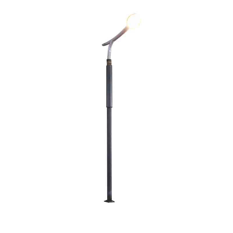 DDK-SSPL-2002 Cylinder Solar Pole With Lamp Head
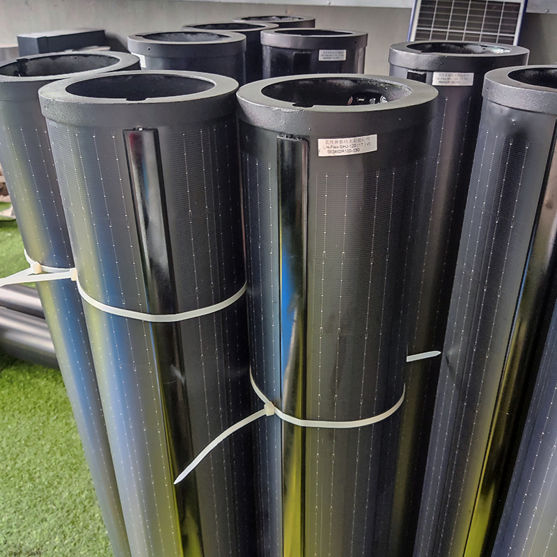 140W Flexible Solar Panel: High-Performance, Elegant and Versatile Power Solution for Lighting Poles and Park Lightings
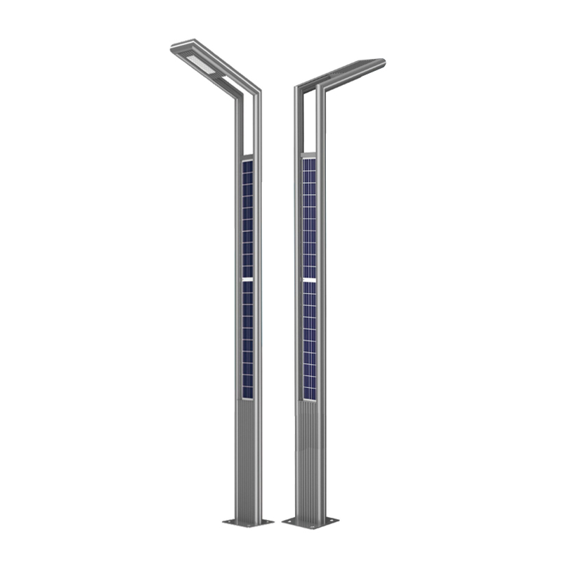 DDK-GN003 Double Sides Integrated Solar Aluminium Pole
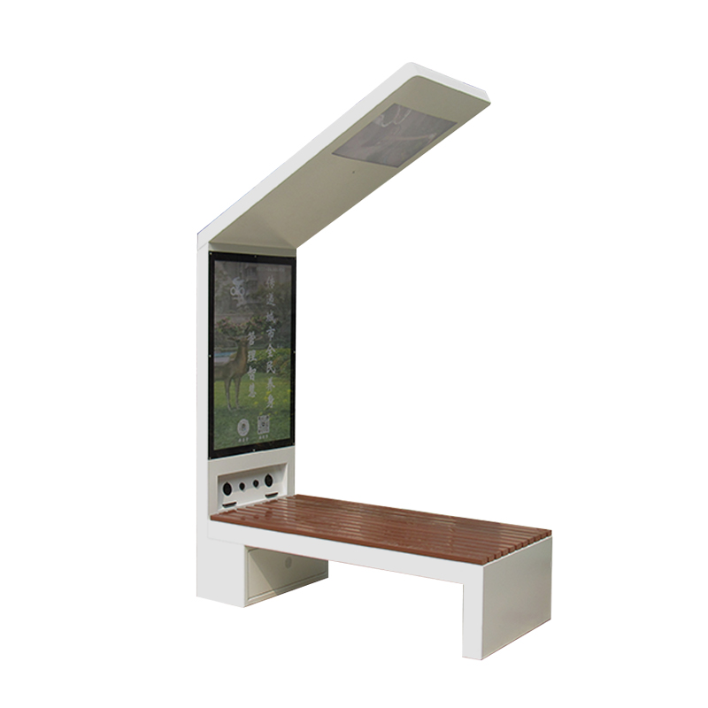 DDK-2000A Charging WIFI Solar Bench Outdoor Bench with Roof on the Top
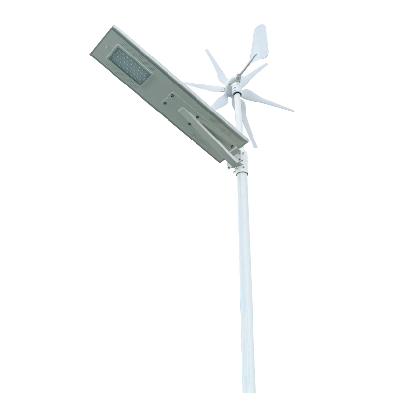 DDK G01 Solar&Wind Hybrid Integrated Optical Lens Solar All in One Light
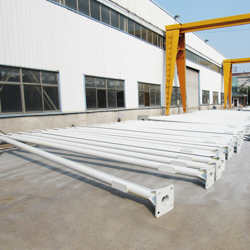 Customized Round Hexagon Octagonal Square Steel Street Light Poles for Outdoor Lightings
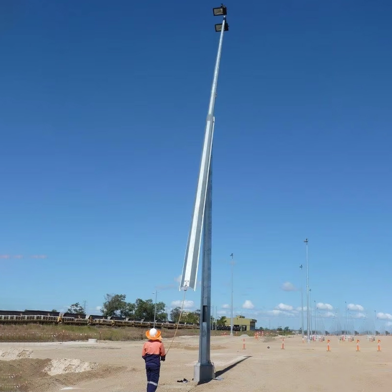 3 to 16M Galvanized Steel Hinged Poles
Contact us
180 meters south of the intersection of Nanbei Avenue and Xuba Road, Gaoyou City, Yangzhou City, Jiangsu Province, China.
+86-18811954888
ddk@cnddk.net
 English
 русский
 Español
 عربى
عربى

