
call us
+86-18811954888
2026-07-23
Understanding the operational lifespan of a flexible solar panel requires examining the underlying materials, environmental conditions, and mechanical stresses that influence these unique photovoltaic systems. While traditional rigid glass panels often remain functional for twenty-five years or more, a flexible solar panel generally offers an operational lifespan ranging between five and fifteen years depending on construction quality and deployment practices. The inherent design choices that make these units lightweight and adaptable also introduce specific vulnerabilities that affect long-term durability. Assessing how long these modules remain effective involves analyzing material composition, degradation rates, environmental exposure, and physical handling during installation and daily use.
Evaluating the operational longevity of a flexible solar panel requires looking beyond simple lifespan estimates. Solar equipment performance shifts gradually over time rather than failing abruptly on a specific date. A panel is considered functional as long as it generates a viable amount of electricity relative to its initial rated capacity.
The baseline lifespan of a flexible solar panel varies considerably based on the core manufacturing technology and the quality of the polymer layers used in its construction. Entry-level units constructed with basic plastic protective coatings often show substantial performance decline within three to five years of continuous outdoor exposure. Higher tier products utilizing advanced fluoropolymer protective coatings can sustain reliable electrical generation for ten to fifteen years under favorable conditions.
The primary distinction in longevity stems from how well the protective layers resist degradation from atmospheric factors. Crystalline silicon cells housed within flexible polymer sheets tend to offer high initial conversion efficiency, but the mechanical rigidity of silicon creates structural vulnerabilities when the panel is flexed repeatedly. Conversely, thin film flexible solar panel options utilizing copper indium gallium selenide or amorphous silicon materials possess higher inherent flexibility, though their initial efficiency metrics and long-term chemical stability differ from silicon-based counterparts.
Discrepancies often exist between the manufacturer warranty period and the actual operational lifespan of a flexible solar panel. Warranties for flexible products typically fall into two categories: product workmanship warranties and power output warranties. Workmanship warranties generally span from one to five years, covering manufacturing defects, junction box separation, and severe structural failures. Power output warranties may extend up to ten years, assuring that the module will produce a designated percentage of its original rated power, often around eighty percent, by the end of the warranty period.
An operational lifespan extends as long as the module continues to generate electricity that serves the energy needs of the user. A flexible solar panel might outlast its formal warranty period by several years if installed in a stable, moderate climate and kept clean. Conversely, harsh environmental conditions or improper installation can cause output to drop below acceptable levels well before the warranty period expires.
All photovoltaic devices experience performance degradation over time due to exposure to sunlight, temperature fluctuations, and environmental moisture. Standard rigid glass modules typically exhibit a degradation rate of approximately point five percent to point eight percent annually. In contrast, a flexible solar panel usually exhibits a higher degradation rate, frequently ranging between one percent and two point five percent per year.
During the initial year of operation, a flexible solar panel may experience a slightly elevated degradation rate as the internal materials settle and adjust to solar radiation and thermal cycling. Subsequent annual degradation usually stabilizes at a steady pace provided the outer protective layers maintain structural integrity. When protective layers degrade or delaminate, moisture and oxygen reach the internal conductive traces, accelerating the degradation rate significantly.
|
Panel Structure Type |
Average Operational Lifespan |
Typical Annual Degradation Rate |
Primary Degradation Driver |
|---|---|---|---|
|
PET Encapsulated Crystalline |
3 to 5 Years |
2.0% to 3.5% |
UV degradation and polymer yellowing |
|
ETFE Encapsulated Crystalline |
8 to 12 Years |
1.0% to 1.8% |
Microcracking and thermal fatigue |
|
Marine-Grade ETFE with Aluminum Substrate |
10 to 15 Years |
0.8% to 1.5% |
Thermal expansion stress |
|
Thin Film CIGS Polymer Composite |
10 to 12 Years |
1.2% to 2.0% |
Moisture vapor permeability |
The longevity of a flexible solar panel is direct function of the raw materials selected during the fabrication process. Because flexible modules lack the rigid aluminum frame and tempered glass cover that protect standard solar modules, every internal layer must provide both flexibility and barrier defense against environmental degradation.
The top transparent layer of a flexible solar panel serves as the primary barrier against ultraviolet radiation, physical abrasion, and atmospheric moisture. Ethylene tetrafluoroethylene, commonly referred to as ETFE, represents a resilient material option for this layer. ETFE features strong chemical resistance, high light transmittance, and a naturally non-adhesive surface that reduces dirt accumulation. Modules constructed with an ETFE top layer resist yellowing and thermal degradation, contributing directly to an extended operational life.
Lower cost modules often employ thermoplastic elastomers or polyethylene terephthalate layers, frequently designated as TPE or PET. While these polymers provide initial transparency and flexibility at a lower price point, they deteriorate more rapidly when exposed to continuous ultraviolet light. Over time, PET and TPE layers tend to develop micro-fissures, turn yellow, and lose transparency, which restricts light from reaching the photovoltaic cells beneath and hastens output reduction.
The internal photovoltaic cell material plays a critical role in determining how a flexible solar panel withstands mechanical handling and physical placement. Monocrystalline silicon cells offer high efficiency in converting sunlight into electricity, but silicon remains a brittle crystalline structure. When integrated into a flexible format, silicon wafers must be sliced extremely thin or segmented into small interconnected nodes. Bending a monocrystalline flexible solar panel beyond its structural limits can cause microscopic fractures across the cell surface, leading to isolated dead zones and permanent power loss.
Thin film technologies, such as copper indium gallium selenide, eliminate brittle crystalline structures entirely by depositing photoactive layers directly onto flexible plastic or metallic foils. Thin film flexible solar panel designs absorb physical bending stresses much better than silicon wafers without developing structural fractures. However, thin film materials can be more sensitive to moisture ingress if the edge seals lose integrity, requiring robust encapsulation techniques to ensure long-term stability.
[Image Placement: A graphic illustration depicting the cross-section layer breakdown of an ETFE flexible solar panel, showing the top protective film, upper EVA layer, solar cell matrix, lower EVA layer, and backing substrate.]
The backing substrate provides structural support for the solar cells and seals the rear side of the module against moisture penetration. Substrates range from lightweight plastic sheets to reinforced fiberglass plates and thin sheet aluminum. Aluminum backings offer beneficial thermal conductivity that aids in dissipating heat, which helps prolong internal component life, though they add minor weight and reduce flexibility. Fiberglass substrates balance rigidity and flex, protecting internal cells against excessive bending.
Encapsulants, typically ethylene-vinyl acetate or advanced polyolefin resins, bond the top protective film, the photovoltaic cell matrix, and the backing substrate together into a single laminated sheet. High quality encapsulation ensures that air pockets are eliminated during manufacture. Air pockets or improper bonding during lamination create localized vulnerabilities where moisture can accumulate, initiating delamination and premature electrical failure.
External ambient conditions exert a continuous influence on the operational integrity of a flexible solar panel. Temperature variations, ultraviolet exposure, moisture exposure, and mechanical motion all interact with the organic polymers and metal interconnects within the module.
Heat management represents a fundamental challenge for flexible solar panel longevity. Rigid solar panels are mounted on metal frames that elevate the glass surface above the installation structure, creating an open air channel that allows heat to escape from the underside of the panel. In contrast, flexible modules are frequently adhered directly to surfaces like vehicle roofs, boat decks, or building structures without an underlying air gap.
Operating without bottom side ventilation causes operating temperatures within a flexible solar panel to climb substantially higher than those in elevated rigid modules. Elevated operating temperatures accelerate chemical degradation within polymer encapsulants and increase electrical resistance across solar cells, reducing overall energy harvest. Furthermore, continuous cycles of heating during the day and cooling at night generate thermal expansion stress, which can weaken solder joints and busbar connections over time.
Ultraviolet radiation from sunlight carries sufficient energy to break chemical bonds within many organic polymers. Over years of outdoor deployment, prolonged exposure to high energy ultraviolet light alters the molecular structure of low grade top sheets and encapsulants, a process known as polymer chain scission.
As polymer chains degrade, the protective layers lose transparency and acquire a yellow or brownish tint. This discoloration acts as a physical filter that blocks specific wavelengths of light from reaching the solar cells, causing a permanent reduction in electrical output. Advanced UV stabilizers incorporated into ETFE and specialized polyolefin encapsulants mitigate this degradation process, preserving optical clarity across extended operational periods.
Polymers are inherently more permeable to moisture vapor than solid tempered glass. Over extended periods, microscopic water vapor molecules can pass through outer polymer layers or seep along the edge seals of a flexible solar panel. Once inside, moisture reacts with metallic interconnections, causing oxidation and corrosion that increases electrical resistance.
Moisture accumulation within internal layers also weakens the adhesive bonds created during lamination. Under repeated heating and cooling, trapped moisture expands and contracts, forcing the polymer layers to separate from the photovoltaic cells. This process, known as delamination, creates visible clouded patches, severely degrades light transmission, and exposes internal electrical traces to rapid atmospheric corrosion.
Physical movement presents a unique operational stressor for flexible photovoltaic devices. While a flexible solar panel is designed to conform to curved surfaces, exceeding the recommended bending radius introduces severe internal mechanical stress. Monocrystalline silicon cells embedded within flexible sheets are particularly susceptible to damage when flexed sharply or subjected to repetitive bending motion.
Microcracks created by excessive flexing may initially be invisible to the naked eye, but they break the continuity of conductive pathways across the silicon cell. As the panel expands and contracts with ambient temperature shifts, these microscopic fissures widen, effectively disconnecting portions of the cell from the circuit. Repetitive motion caused by strong winds or vehicle movement can gradually degrade total power production as microcracking spreads across multiple cells.
Operating conditions vary dramatically based on where and how a flexible solar panel is installed. Real-world longevity reflects the unique combination of environmental hazards and mechanical demands present in specific deployment environments.
Installing a flexible solar panel on a boat, yacht, or marine vessel introduces significant environmental stress. Marine environments feature constant exposure to saltwater spray, high humidity, intense ultraviolet reflections off water surfaces, and continuous dynamic motion as the vessel moves through waves.
Saltwater accelerates the oxidation of exposed electrical terminals and junction boxes if seals are compromised. Additionally, salt crust build-up on the panel surface absorbs moisture and lowers light transmission, requiring frequent washing with fresh water. High quality ETFE panels designed specifically for marine applications utilize specialized edge sealing compounds and corrosion resistant junction boxes to achieve operational lifespans of eight to twelve years under marine conditions.
Recreational vehicles and camper vans represent popular applications for a flexible solar panel due to aerodynamic constraints and weight limitations. When applied directly to an RV roof using industrial adhesives, the panel experiences continuous vibration while driving, variable wind forces, and extreme temperature fluctuations on black or dark vehicle surfaces.
A major challenge in RV applications involves thermal retention from direct surface mounting. Without an airflow gap under the panel, roof temperatures on summer days can exceed high thermal thresholds, accelerating heat induced degradation of the underlying adhesive and the panel encapsulant. Utilizing mounting techniques that introduce a minimal ventilation space beneath the flexible module helps preserve panel efficiency and prevents early thermal failure.
[Image Placement: A photo illustrating a flexible solar panel mounted on the curved roof of a camper van, showing clean cable routing into a sealed roof entry housing.]
Portable field uses, such as camping or temporary field power setups, subject a flexible solar panel to frequent handling, packing, unrolling, and transport. Portable panels encounter mechanical risks including impact from dropped equipment, accidental stepping, and sharp bending during storage.
When deployed in fixed off-grid cabin installations on stable backing structures, flexible panels experience significantly fewer mechanical stresses than portable units. Fixed installations where the panel is protected from excessive movement and supported by a uniform backing plate frequently attain the upper boundaries of expected lifespan, remaining operational for ten years or more.
|
Application Environment |
Primary Environmental Hazards |
Typical Lifespan Range |
Recommended Maintenance Focus |
|---|---|---|---|
|
Marine & Saltwater Vessels |
Salt spray corrosion, structural flexing, UV reflection |
7 to 11 Years |
Freshwater rinsing, inspection of junction box seals |
|
RV & Camper Roofs |
Thermal build-up, highway vibration, wind shear |
6 to 10 Years |
Thermal clearance checking, adhesive border checks |
|
Fixed Off-Grid Structures |
Temperature cycling, snow loading, atmospheric dust |
8 to 12 Years |
Dust removal, inspection of edge sealant integrity |
|
Portable Field Deployments |
Excessive bending, surface abrasion, impact damage |
3 to 6 Years |
Proper rolling/flat storage, surface scratch prevention |
Understanding the pathways that lead to premature failure helps users identify early warning signs and implement preventative measures to extend the usable life of their solar equipment.
Electrical interconnections within a flexible solar panel consist of thin metallic ribbons, known as busbars, soldered across the surfaces of adjacent cells. These metallic interconnects possess different thermal expansion coefficients than the surrounding polymer layers and silicon wafers.
When a flexible solar panel experiences rapid temperature shifts or repeated mechanical flexing, stress concentrates at the solder joints connecting the busbars to the cells. Over time, this stress leads to solder fatigue, micro-fracturing, and eventual shearing of the metal traces. A severed busbar creates an open circuit across that cell section, forcing power output to drop significantly or cease altogether.
Hotspots occur when localized areas of a solar panel become shaded, soiled, or damaged while the rest of the panel remains exposed to full sunlight. The unshaded cells continue generating electrical current, which forces energy through the shaded, non-generating cell. The shaded cell acts as a resistor, converting that electrical energy into localized heat.
Because flexible solar panels feature lower thermal dissipation capabilities than glass modules, hotspots can reach high temperatures quickly. Excessive heat at a single point can melt internal polymer encapsulants, scorch the backing substrate, and permanently damage adjacent cells. In severe instances, unresolved hotspots lead to burn-through spots on the outer protective layer, allowing moisture direct entry into the internal assembly.
Flexible modules are commonly attached to mounting surfaces using pressure sensitive structural adhesives, silicone sealants, or specialized double-sided tapes. Over years of outdoor exposure, moisture, chemical pollutants, and ultraviolet radiation weaken these adhesive layers.
If the adhesive bond between the panel backing and the mounting surface deteriorates unevenly, air pockets can form beneath the panel. These pockets trap heat and allow wind forces to pull at the unbonded edges during transport. Partial substrate separation exposes the rear side of the panel to moisture accumulation and increases the likelihood of mechanical flexing during high wind events.
Implementing proper handling, installation, and maintenance procedures substantially increases the probability that a flexible solar panel will reach or exceed its expected operational lifespan.
To mitigate heat retention issues associated with direct surface mounting, installation techniques should incorporate small air gaps or thermally conductive spacer layers beneath the module. Installing thin corrugated plastic sheets, marine grade mesh, or aluminum mounting channels beneath the panel elevates the unit slightly above the mounting surface.
This elevated structure permits airflow under the rear substrate, reducing peak operating temperatures by a noticeable margin during hot summer days. Cooler operating conditions reduce thermal stress on internal polymer layers, help maintain higher electrical efficiency, and reduce the rate of heat induced material degradation.
[Image Placement: Diagram demonstrating a ventilated mounting method for a flexible solar panel using twin-wall polycarbonate backing sheets to create an airflow channel above an RV roof.]
Accumulating dust, sea salt residues, bird droppings, and tree sap reduces light transmission and increases the risk of hotspot formation. Regular cleaning maintains optimal light absorption and protects the outer protective layer from chemical attack.
Cleaning a flexible solar panel requires non-abrasive techniques to prevent scratching the soft outer polymer sheet:
Use soft microfiber cloths or non-abrasive sponges paired with clean water.
Avoid harsh chemical solvents, acidic cleaners, or abrasive powders that erode protective coatings.
Clean panels during early morning or late evening hours when surface temperatures are cool to avoid thermal shock.
Rinse thoroughly with fresh water in marine settings to remove salt crystal deposits.
Careful handling during unboxing, storage, and installation prevents structural damage to internal cell matrices and busbar connections. Observing structural limits ensures that internal components remain intact throughout the installation process.
Adhering to specific operational rules minimizes mechanical stress during handling:
Never exceed the minimum bend radius specified by the manufacturer, which usually ranges between thirty and thirty-five degrees of curvature.
Avoid bending the panel sharply at corners or near the junction box housing.
Support the panel across its entire length during transport rather than carrying it by one edge or by the output cables.
Avoid resting heavy tools or sharp objects on the surface of the panel during installation.
Ensure the mounting surface is thoroughly cleaned and free of debris prior to applying adhesives to guarantee uniform adhesion.
Related Products
 DDK-SSPL-2000 Cylinder Solar Pole Single/Double Arms And Street LED Lamps
 DDK-SSPL-2002 Cylinder Solar Pole With Lamp Head
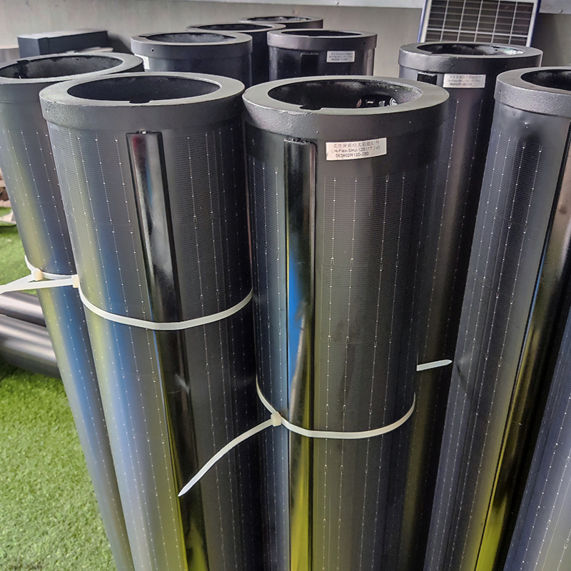 140W Flexible Solar Panel: High-Performance, Elegant and Versatile Power Solution for Lighting Poles and Park Lightings
 DDK-GN003 Double Sides Integrated Solar Aluminium Pole
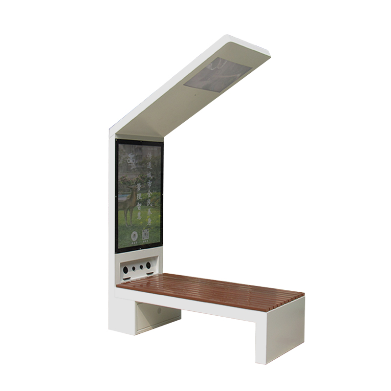 DDK-2000A Charging WIFI Solar Bench Outdoor Bench with Roof on the Top
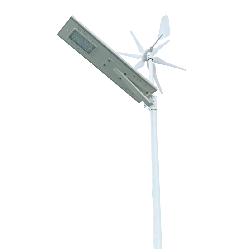 DDK G01 Solar&Wind Hybrid Integrated Optical Lens Solar All in One Light
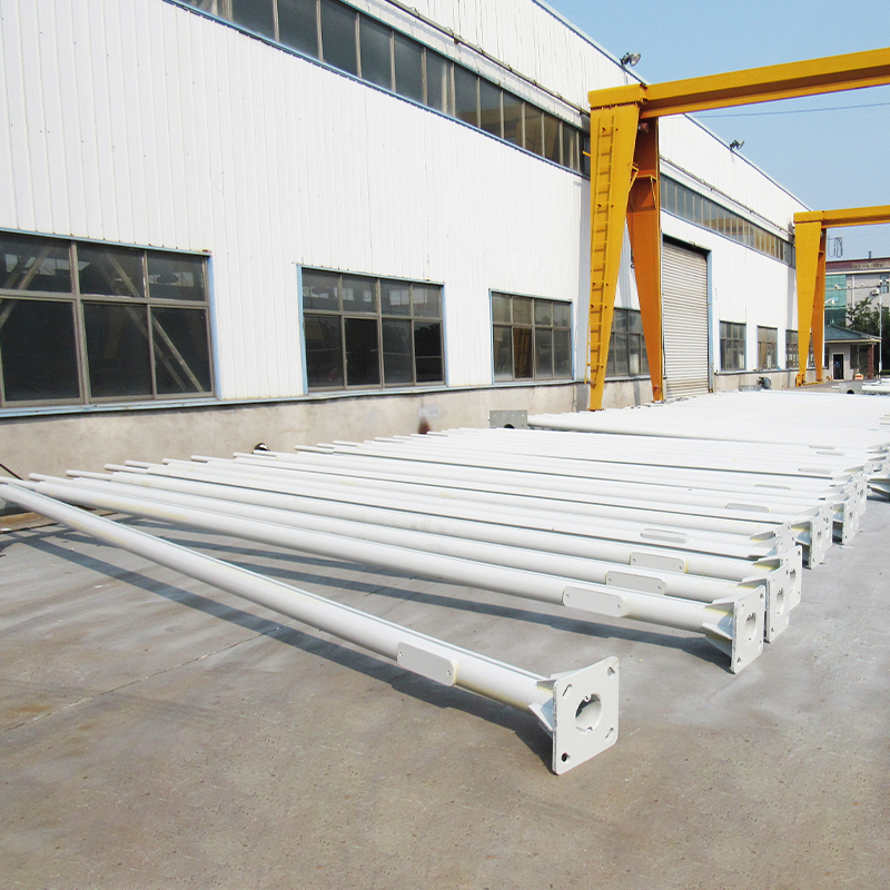 Customized Round Hexagon Octagonal Square Steel Street Light Poles for Outdoor Lightings
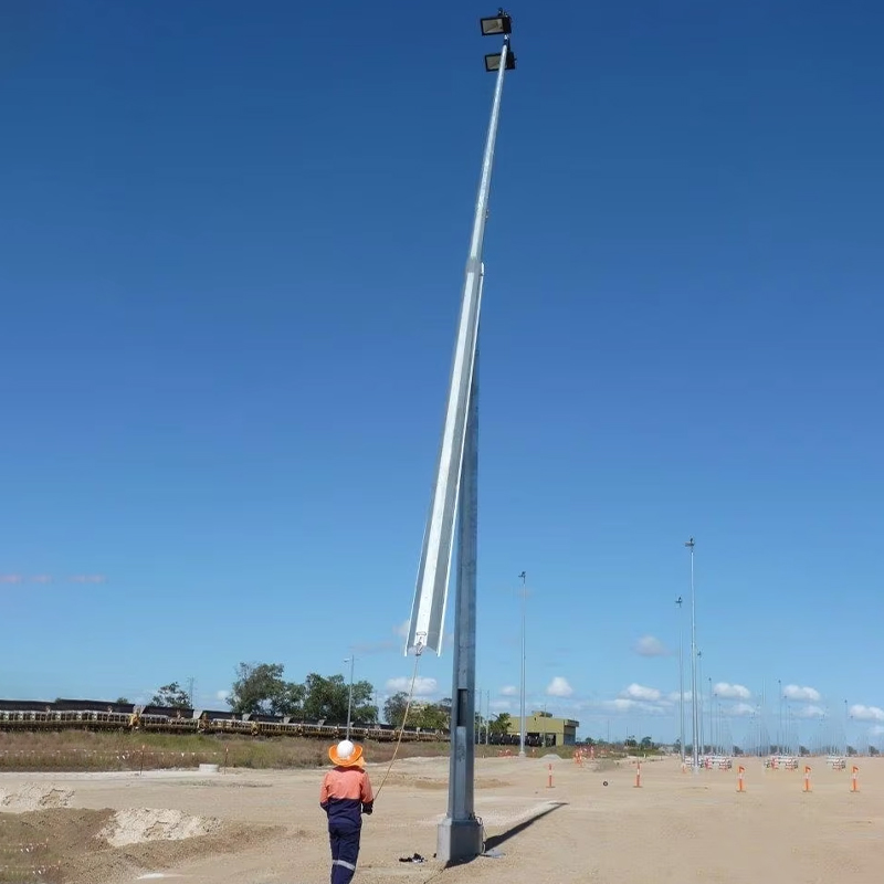 3 to 16M Galvanized Steel Hinged Poles
Contact us
180 meters south of the intersection of Nanbei Avenue and Xuba Road, Gaoyou City, Yangzhou City, Jiangsu Province, China.
+86-18811954888
ddk@cnddk.net
 English
 русский
 Español
 عربى
عربى

