call us
+86-18811954888
2026-04-23
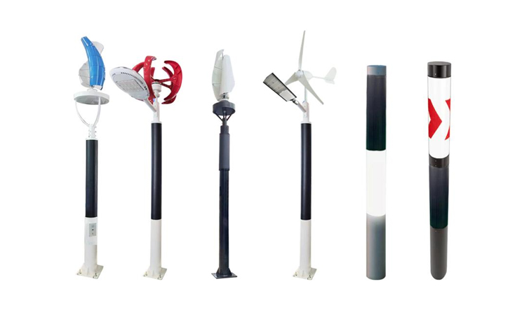
Street Light Poles, Outdoor Street Lights, and Solar Poles are the physical infrastructure backbone of public and commercial outdoor lighting worldwide, yet the detailed technical questions surrounding their design, service life, height, installation, and performance are rarely addressed in accessible, practical depth outside of specialist engineering publications. Whether you are a municipal lighting engineer, a property developer specifying lighting for a new subdivision, a facilities manager responsible for an existing pole network, or an installer preparing to commission a new solar lighting system, the answers to questions like what is the life expectancy of a street light pole, how tall is a street light, how tall is a light pole, how do street lights work, and what is the optimal angle for solar panel mounting on Solar Poles are all fundamental to making good decisions and achieving long term system performance.
The direct answers to these core questions are as follows. The life expectancy of a street light pole depends on the material and environment but is typically 25 to 50 years for steel poles with adequate corrosion protection, 50 to 80 years or more for concrete poles, and 20 to 30 years for aluminum poles in standard conditions. How tall is a street light depends on the road type: 5 to 6 meters for pedestrian paths, 8 to 12 meters for collector roads, and 12 to 20 meters for major arterial roads. How tall is a light pole in parking, park, and commercial landscape applications ranges from 4 to 10 meters depending on the coverage area and aesthetic requirements. The installation of solar street light involves a systematic process of site assessment, foundation preparation, pole erection, and panel and luminaire commissioning that takes 2 to 4 hours per pole for experienced installers. The tilt angle of solar panel on Solar Poles is typically set equal to the geographic latitude of the installation site plus or minus 5 to 15 degrees depending on seasonal energy priority. The optimal angle for solar panel output is the latitude matched angle for year round balanced performance, or latitude plus 10 to 15 degrees for winter priority installations in temperate climates. And how do street lights work involves the interaction of a power source, a photocell or smart controller, a driver circuit, and an LED or other light source that together produce reliable, scheduled illumination. This article covers all of these questions in full technical depth.
The question of what is the life expectancy of a street light pole has no single answer because pole service life is determined by the combination of pole material, protective treatment, environmental exposure, maintenance quality, and structural loading history. Street Light Poles that are regularly inspected, repainted, or recoated when protective finishes deteriorate, and that have not been subjected to vehicle impact or extreme wind events, routinely exceed their design service life, while poles in coastal, high humidity, or heavily salted road environments that receive inadequate maintenance can show structural deterioration within 10 to 15 years of installation.
Steel is the most widely used material for Street Light Poles in most countries, valued for its high strength to weight ratio, ease of fabrication, and the ability to achieve a wide range of cross sectional shapes and heights through standard manufacturing processes. Hot dip galvanized steel poles (where the steel is immersed in molten zinc to create a metallurgically bonded zinc coating) represent the standard specification for most municipal applications, with the zinc coating providing cathodic protection to the steel beneath even if the coating is scratched or damaged. Hot dip galvanized steel Street Light Poles with adequate zinc coating thickness (typically 85 microns average for poles in ASTM A123 Grade 45 specification) achieve service lives of 25 to 50 years in inland non coastal environments, reducing to 15 to 30 years in coastal zones with regular salt spray exposure, and potentially below 20 years in highly aggressive industrial or marine environments without supplementary protective coatings.
The primary failure mechanism of steel Street Light Poles is corrosion at the base of the pole, in the zone between 300 mm above and 300 mm below the ground surface, where alternating wet and dry conditions, soil chemistry, and the crevice between the pole and the concrete foundation create a particularly aggressive corrosion environment. This is why regular base inspection, cleaning, and recoating of steel poles is the most critical maintenance activity for extending their service life. Many pole failures attributed to age are actually failures caused by untreated base corrosion that develops over 10 to 20 years while the above ground portion of the pole appears structurally sound.
Prestressed or reinforced concrete Street Light Poles offer the longest service life of any common pole material, with well constructed concrete poles in non aggressive environments routinely providing 50 to 80 years of service without significant structural degradation. The corrosion resistance of concrete poles in normal soil and atmospheric conditions is essentially unlimited from a structural standpoint, since the concrete matrix is not subject to the electrochemical corrosion that limits steel pole life. The main long term durability concern for concrete poles is reinforcement corrosion caused by chloride penetration from road salt or marine spray, which can cause cracking and spalling of the concrete cover above the reinforcing steel after 20 to 40 years in aggressive environments. In tropical climates with high UV intensity and frequent wet dry cycles, spun concrete poles with dense, well compacted concrete and adequate cover to the reinforcement (minimum 25 mm in non aggressive environments, 40 mm in marine zones) consistently demonstrate service lives of 50 years or more with minimal maintenance beyond periodic washing to remove surface deposits.
Aluminum alloy Street Light Poles are specified in architectural and commercial landscape applications where the lightweight of aluminum simplifies installation and where the natural anodized or powder coated finish provides acceptable appearance with minimal maintenance. The service life of aluminum poles is typically 20 to 30 years in standard environments, with the primary degradation mechanism being surface oxidation and pitting in chloride rich coastal environments rather than the through wall corrosion that affects steel. The mechanical strength of aluminum is lower than steel at equivalent weight, making aluminum poles generally suitable for lower height (below 10 meters) Outdoor Street Lights applications rather than the higher load high mast Street Light Poles used on major roads.
Regardless of pole material, the single most effective action for maximizing the life expectancy of a street light pole is regular systematic inspection. Industry best practice, reflected in standards such as ANSI/NAAMM MH 26, recommends visual inspection of Street Light Poles at 1 to 2 year intervals and structural integrity assessment at 5 year intervals for poles over 25 years old. Inspection should specifically assess: base corrosion condition (using a chain wrap or hammer tap test to detect hollow wall corrosion in steel poles), bolt and foundation integrity, handhole cover condition and sealing, any signs of vehicle impact distortion, and luminaire mounting arm condition. Poles showing more than 10 percent cross sectional area loss at the critical base zone should be scheduled for replacement regardless of their above ground visual appearance.
The height of a Street Light Pole or Outdoor Street Lights installation is one of the primary design variables in any street lighting project, because it directly determines the illuminated area per pole, the uniformity of illuminance across the road surface, the required luminous output of the luminaire, and the structural loading on the pole from wind and the luminaire weight. There is no single answer to how tall is a street light because the optimal height depends on the road classification, the required illuminance level, the pole spacing being used, and the type of luminaire distribution being applied.
| Application Type | Typical Pole Height | Typical Pole Spacing | Target Illuminance |
|---|---|---|---|
| Garden path and park walkway | 3 to 5 meters | 10 to 20 meters | 3 to 10 lux |
| Pedestrian road and cycleway | 5 to 7 meters | 15 to 30 meters | 5 to 15 lux |
| Residential local road | 6 to 8 meters | 25 to 40 meters | 5 to 15 lux |
| Collector and distributor road | 8 to 12 meters | 30 to 50 meters | 15 to 30 lux |
| Primary arterial road | 10 to 15 meters | 35 to 55 meters | 20 to 30 lux |
| Motorway and expressway | 12 to 20 meters | 40 to 60 meters | 10 to 30 lux |
The relationship between Street Light Poles height and illuminance on the road surface follows the inverse square law of illumination: doubling the mounting height reduces the illuminance directly beneath the pole to one quarter of its previous value, but increases the area illuminated at a given lux level. This relationship means that taller poles with higher output luminaires can achieve the same average illuminance on a road surface with wider pole spacing, reducing the total number of poles required for a given road length. For a typical collector road designed for 20 lux average illuminance, a 10 meter pole with a 10,000 lumen LED luminaire at 35 meter spacing achieves comparable performance to an 8 meter pole with a 6,000 lumen luminaire at 25 meter spacing, with the taller option requiring approximately 30 percent fewer poles and therefore lower civil infrastructure cost despite the higher individual pole and luminaire cost.
Solar Poles for standalone solar street light systems add a height design consideration beyond the standard photometric calculation: the photovoltaic panel at the top of the pole must not be shaded by adjacent poles, trees, buildings, or other obstructions during the hours when solar energy generation is most productive (typically 9 AM to 3 PM). For a Solar Poles installation along a road where panels face south (in the northern hemisphere) or north (in the southern hemisphere), the minimum pole spacing to avoid inter pole panel shading depends on the pole height and the solar panel inclination angle. A general rule is that the clear distance between poles should be at least 3 times the combined height of the pole and the vertical projection of the tilted panel to prevent shading during low sun angle conditions in winter.
Understanding how do street lights work at the system level, covering the power delivery, the control mechanism, the light source technology, and the optical distribution, is the knowledge foundation for specifying, installing, and maintaining Outdoor Street Lights effectively. Modern street lighting systems, whether grid powered LED units on conventional Street Light Poles or solar powered LED systems on Solar Poles, share the same functional architecture of power input, control circuit, driver, and light source, differing primarily in how the power is delivered to the driver stage.
Grid powered Outdoor Street Lights receive alternating current (typically 220 to 240 volts at 50 Hz in most of the world, or 110 to 120 volts at 60 Hz in North America) through underground cable circuits connected to a distribution substation or a local supply point. The cable circuit is typically 3 phase for large networks, with individual poles connected single phase from the distribution cable, allowing the load to be balanced across the three phases. The cable route follows the pole line and is usually buried at a minimum depth of 450 to 600 mm below the road or footpath surface in conduit or direct burial cable specification approved for outdoor underground use.
Solar Poles receive their power from the photovoltaic panel mounted at the top of the pole, which generates direct current (DC) proportional to the incident solar irradiance. This DC output is fed to a charge controller that regulates battery charging to prevent overcharging and protects the battery from deep discharge. The battery stores the daytime solar energy and supplies it to the LED luminaire driver during the night operating period. A well designed Solar Poles system with appropriate panel size, battery capacity, and LED wattage can provide reliable illumination through 3 to 5 consecutive nights without solar input, making it effective in locations that experience extended cloudy periods characteristic of maritime and temperate climates.
The most common control method for Outdoor Street Lights is the photocell or photoelectric cell, a light sensitive semiconductor device mounted on or near the luminaire that measures ambient light intensity. The photocell activates the lamp circuit when ambient light drops below approximately 35 lux (equivalent to deep twilight conditions) and deactivates it when ambient light rises above approximately 70 lux (to prevent oscillation caused by clouds partially blocking the sun). The photocell is a simple, reliable, and low cost control method that requires no programming or network connection and operates autonomously as long as it has power. Photocells have a rated service life of 10 to 15 years and should be replaced when they reach this age even if still apparently functional, as degraded photocells that switch at incorrect light levels cause either wasted electricity (leaving lights on unnecessarily during daylight) or reduced illumination hours (switching lights off before full darkness).
Astronomical time clocks are used either as a primary control method or as a backup to photocells, calculating the exact sunset and sunrise times for the installed geographic location from a programmed coordinate and date, and switching the street light circuit at these calculated times regardless of actual ambient light conditions. Modern smart controls for Outdoor Street Lights go further, using networked communication (DALI 2, Zhaga, Zigbee, or LoRa protocols) to allow individual luminaire monitoring and dimming from a central management platform, enabling energy savings of 30 to 50 percent through adaptive dimming of circuits during low traffic overnight periods.
Modern Outdoor Street Lights use LED light sources driven by electronic constant current driver circuits. The driver converts the supply voltage (AC mains for grid powered units, DC battery for Solar Poles systems) to the specific regulated current required by the LED array, maintaining this current constant regardless of supply voltage variations and LED forward voltage changes with temperature. The constant current driver is the critical component for LED service life: LED arrays driven at constant current with low ripple experience much lower thermal and electrical stress than equivalent LEDs driven by simpler circuits with high ripple current, and the quality of the driver is typically the primary determinant of LED luminaire field service life.
Modern LED street luminaires rated at 130 to 200 lumens per watt represent energy savings of 40 to 65 percent compared to the high pressure sodium (HPS) luminaires they replace, and their rated service life of 50,000 to 100,000 hours to L70 (the point where output depreciates to 70 percent of initial value) is 3 to 6 times longer than HPS lamp life, dramatically reducing the maintenance frequency and cost of the overall Street Light Poles and luminaire system over its operating period.
The installation of solar street light on Solar Poles is a distinct technical process from conventional grid powered street light installation, involving additional considerations for panel orientation, battery installation, charge controller setup, and system commissioning that are specific to the off grid solar power architecture. A systematic installation process completed by trained personnel produces a system that will operate reliably for 8 to 12 years before major component replacement is required; a poorly executed installation can result in premature battery failure, inadequate charge, or commissioning errors that are difficult to diagnose and correct after the pole is erected.
Before any foundation work begins, each proposed Solar Poles location must be assessed for solar access to confirm that the panel will receive adequate unobstructed sunlight throughout the year. The site assessment should evaluate:
The tilt angle of solar panel on Solar Poles is the angle between the face of the photovoltaic panel and the horizontal plane, measured in degrees. It is one of the most technically significant installation parameters for any solar power system because it directly determines how much solar irradiance the panel face receives throughout the year, which in turn determines the daily and annual energy output of the panel and therefore the adequacy of the solar system for its intended load. Understanding both the general principle of the optimal angle for solar panel and the specific adjustment rationale for different seasonal priorities is essential for correctly specifying and commissioning Solar Poles systems.
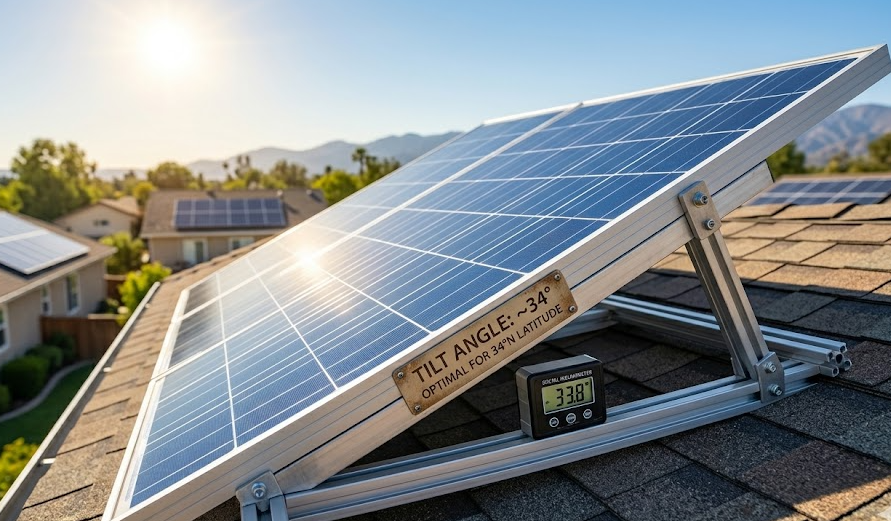
The fundamental principle governing optimal angle for solar panel is that the panel face should be oriented perpendicular to the mean solar radiation vector for the location and season of interest. Since the sun's apparent path in the sky changes with the seasons (higher in summer, lower in winter), the angle at which a tilted fixed panel best intercepts this radiation also changes seasonally. For a year round balanced energy production objective, the optimal tilt angle for a fixed panel in the northern hemisphere is approximately equal to the geographic latitude of the installation, and the panel should face true south. For an installation in the southern hemisphere, the equivalent optimal angle is also approximately equal to the geographic latitude, but the panel faces true north.
As a practical guide: a solar street light in Bangkok, Thailand (latitude approximately 14 degrees north) should have its panel tilted at 14 degrees from horizontal facing due south; a system in Madrid, Spain (latitude approximately 40 degrees north) should be set at 40 degrees; and a system in Oslo, Norway (latitude approximately 60 degrees north) should be tilted at 60 degrees. Each of these settings provides the best year round average energy yield for the respective location, typically producing annual energy output within 5 percent of the theoretical maximum achievable with a two axis sun tracking system.
The tilt angle of solar panel can be adjusted from the latitude matched angle to prioritize either summer or winter energy production depending on the seasonal lighting demand profile of the application:
A practical benefit of steeper panel tilt angles on Solar Poles in dusty, arid, or polluted environments is improved self cleaning during rainfall events. Panels tilted at 30 degrees or more shed rain water at sufficient velocity to carry accumulated dust and debris off the panel face, while panels tilted at less than 15 degrees tend to retain water in surface tension and allow debris to settle as the water evaporates, forming a thin soil crust that accumulates across the panel surface and can reduce output by 5 to 20 percent in dry seasons. For Solar Poles installations in semi arid regions with infrequent rainfall, specifying a tilt angle toward the upper end of the optimal range (latitude plus 10 to 15 degrees) provides an indirect self cleaning benefit in addition to the winter energy optimization advantage.
The final selection of Street Light Poles type, Outdoor Street Lights specification, and Solar Poles configuration for any given project involves balancing the performance, cost, service life, and practical installation considerations specific to the site and application. The following selection guidance covers the most common project types encountered in municipal, commercial, and residential outdoor lighting.
Solar Poles are the preferred specification over grid powered Street Light Poles in the following circumstances:
The structural specification of Street Light Poles increases significantly with height, because the overturning moment at the pole base (which is what the foundation and the pole cross section must resist) increases with both the square of the height (for wind load on the pole itself) and linearly with height (for the wind load on the luminaire and, for Solar Poles, the photovoltaic panel). A 12 meter steel Street Light Pole in a 120 km/h design wind zone must resist a base overturning moment approximately 4 times greater than an equivalent 6 meter pole of the same cross section and luminaire specification, requiring either a larger pole diameter, a heavier wall thickness, or a deeper foundation, all of which increase the installed cost substantially. This structural cost escalation with height is one of the reasons that photometric design optimization (choosing the minimum adequate pole height for the required illuminance standard rather than defaulting to the tallest available pole) is important for project cost management in Street Light Poles procurement.
A proactive maintenance program for Street Light Poles, Outdoor Street Lights, and Solar Poles significantly extends the effective service life of all system components and prevents the accelerated deterioration that leads to early unplanned replacement. The following maintenance priorities apply across all pole and luminaire types:
Illuminating Engineering Society (2014). ANSI/IES RP 8 14: Roadway Lighting. IES, New York.
National Association of Architectural Metal Manufacturers (2015). ANSI/NAAMM MH 26: Guide Specifications for the Design of Metal Flagpoles and Lighting Standards. NAAMM, Chicago, IL.
Duffie, J. A., and Beckman, W. A. (2013). Solar Engineering of Thermal Processes, 4th edition. Wiley, Hoboken, NJ. (Optimal solar panel angle and seasonal tilt calculations.)
International Energy Agency (2020). World Energy Outlook 2020: Solar PV Technology. IEA, Paris.
ASTM International (2017). ASTM A123/A123M: Standard Specification for Zinc (Hot Dip Galvanized) Coatings on Iron and Steel Products. ASTM, West Conshohocken, PA.
Luque, A., and Hegedus, S. (Eds.) (2011). Handbook of Photovoltaic Science and Engineering, 2nd edition. Wiley, Chichester, UK.
Commission Internationale de l'Eclairage (2010). CIE 115: Lighting of Roads for Motor and Pedestrian Traffic. CIE, Vienna.
Standards Australia (2016). AS/NZS 1158: Lighting for Roads and Public Spaces. SAI Global, Sydney.
Diaf, S., Diaf, D., Belhamel, M., Haddadi, M., and Louche, A. (2007). A methodology for optimal sizing of autonomous hybrid PV/wind system. Energy Policy, 35(11), 5708–5718.
U.S. Department of Energy (2022). Solar Energy Technologies Office: Solar Photovoltaic System Performance. DOE, Washington, DC.
Related Products
 DDK-SSPL-2000 Cylinder Solar Pole Single/Double Arms And Street LED Lamps
 DDK-SSPL-2002 Cylinder Solar Pole With Lamp Head
 140W Flexible Solar Panel: High-Performance, Elegant and Versatile Power Solution for Lighting Poles and Park Lightings
 DDK-GN003 Double Sides Integrated Solar Aluminium Pole
 DDK-2000A Charging WIFI Solar Bench Outdoor Bench with Roof on the Top
 DDK G01 Solar&Wind Hybrid Integrated Optical Lens Solar All in One Light
 Customized Round Hexagon Octagonal Square Steel Street Light Poles for Outdoor Lightings
 3 to 16M Galvanized Steel Hinged Poles
Contact us
180 meters south of the intersection of Nanbei Avenue and Xuba Road, Gaoyou City, Yangzhou City, Jiangsu Province, China.
+86-18811954888
ddk@cnddk.net
 English
 русский
 Español
 عربى
عربى
